Split-chamber rotary engine

a rotary engine and split-chamber technology, applied in the direction of liquid fuel engines, machines/engines, combination engines, etc., can solve the problems of inefficiency of the reciprocating piston internal combustion engine principle, inability to achieve the effect of increasing the torque output of the engine, high resistance to detonation, and efficient operation

Active Publication Date: 2011-11-15
DE OLIVEIRA EGIDIO L
View PDF40 Cites 10 Cited by
  • Summary
  • Abstract
  • Description
  • Claims
  • Application Information

AI Technical Summary

Benefits of technology

[0016]Because of the configuration of the split-chamber rotary engine, with its separate compression and power modules, multiple power events can occur with each rotation of the rotor, depending upon the number of combustion chambers built into the rotor and the number of compression modules provided, as well as the number of rotors in a multiple rotor configuration. This increases the torque output of the engine at relatively low rpm when compared to conventional engines. The ability to selectively engage a multiplicity of rotors and compressor modules besides selectively triggering combustion for the individual rotor chambers by simple control devices enable this engine to operate efficiently over a wide range of power demands, thus eliminating the need for mechanical gear boxes.
[0017]The split-chamber rotary engine has no wasted motion of reciprocating components and corresponding wasted fuel. The rotary engine is also highly resistant to detonation, as the opposing walls of the compression piston and rotor chamber are free to move and absorb shock waves. Fuel is introduced via a direct injection system at the combustion chamber, mixing with the air charge contained therein. These characteristics allow the use of fuels having relatively low octane or anti-knock ratings, as well as relatively heavy and low cost fuel oils, to operate the engine. Alternatively, one or more carburetors may be installed externally to the compressor, if some sacrifice of efficiency is acceptable.

Problems solved by technology

Nonetheless, the reciprocating piston internal combustion engine principle, by its nature, is not particularly efficient.
The major problem is that this engine configuration combines the function of an air compressor for drawing in and compressing the intake charge and expelling the exhaust gases with the function of an expansion motor for using the power produced by the combustion of the air and fuel mixture in a single chamber.
However, the power stroke of the reciprocating piston engine is relatively inefficient.
However, here the piston is at mid-stroke and the energy of the mixture is about half-spent.
The overall result is an engine configuration that is not optimized for efficiency.

Method used


Image

  • Split-chamber rotary engine
  • Split-chamber rotary engine
  • Split-chamber rotary engine

Examples


Embodiment Construction

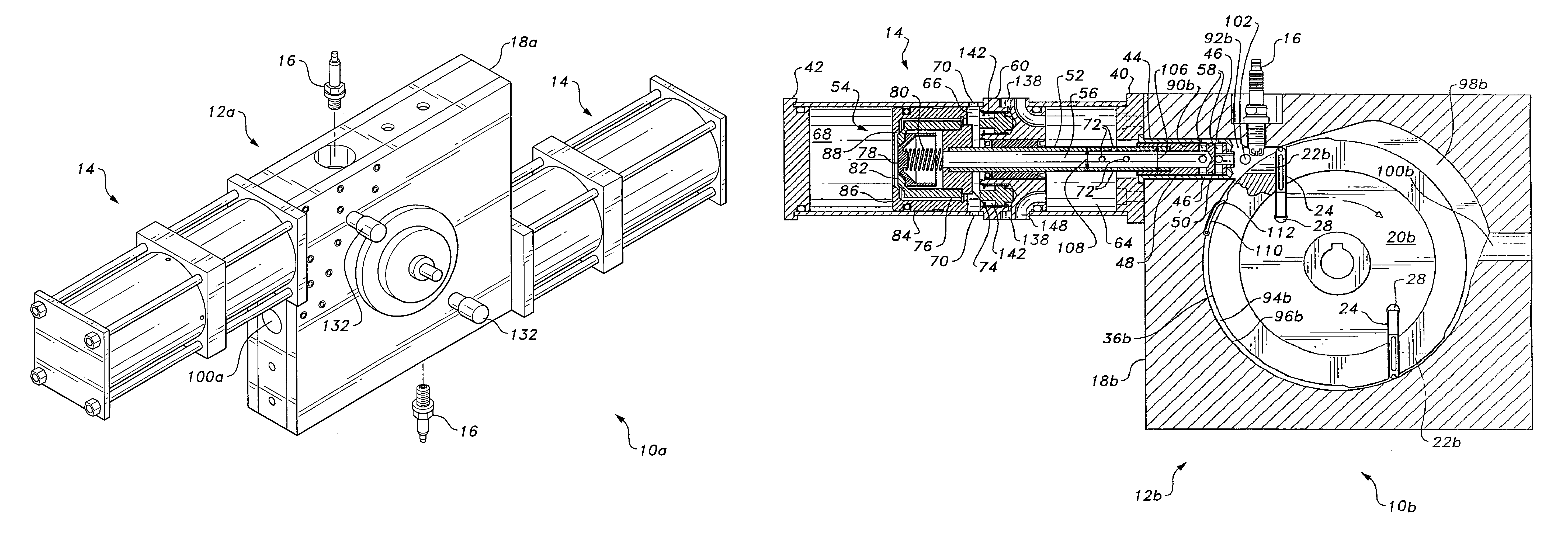
[0032]The rotary engine has a power module that comprises a rotor disposed within a case and at least one compression module that comprises a reciprocating piston assembly actuated by pneumatic or combustion pressure from the power module. The engine may have various embodiments that differ according to different numbers of combustion chambers within the rotor, different numbers of compression modules, and / or single or multiple rows of compression and power modules, as desired.

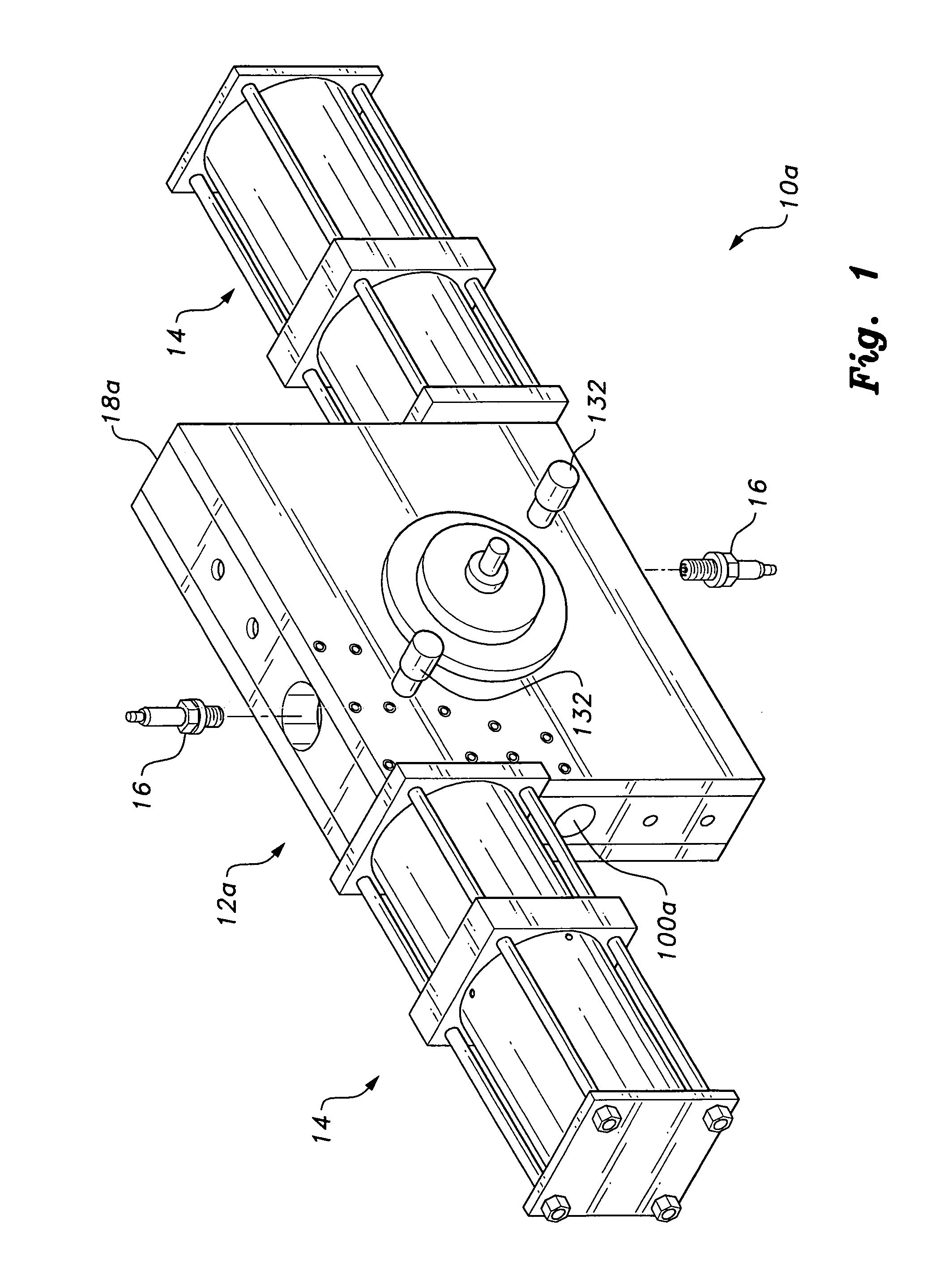
[0033]FIG. 1 provides a perspective view of a first embodiment of the engine 10a, having a power module 12a with two identical compression or compressor modules 14. Conventional spark plugs 16, or glow plugs for starting in a diesel engine, are provided, with one spark plug or glow plug 16 located at the juncture of each compressor module with the rotor chamber within the power module 12a, discussed further below. The power module 12a comprises a case 18a having a rotor therein, e.g. rotor 20a, a portion of wh...


PUM


Abstract

The split-chamber rotary engine includes a rotary power module having a case with a circular rotor installed therein. At least one, and preferably two or more combustion chambers are formed peripherally in the rotor. The generally circular rotor cavity of the case includes at least one, and preferably two or more, peripheral expansion chambers. A corresponding number of reciprocating compressor modules are installed upon the case, with the compressor module axis being aligned generally tangentially to the rotor periphery. The compressor module includes concentric reciprocating pistons and valves that compress the air charge and transfer the compressed charge to the rotary power module for power production. The compressor module is driven purely by combustion gas pressure acting upon its inboard piston. No mechanical linkage exists from power module to compressor module. The engine may include multiple rotor and case rows, as desired.

Description

BACKGROUND OF THE INVENTION[0001]1. Field of the Invention[0002]The present invention relates generally to internal combustion engines, and particularly to a split-chamber rotary engine that combines mechanically independent rotary and reciprocating features, including a rotary power module with one or more reciprocating compressor modules.[0003]2. Description of the Related Art[0004]Innumerable different configurations of internal combustion engines and expansion motors have been developed in the past. The reciprocating piston internal combustion engine commonly known as the piston engine in its various forms (e.g., two-stroke and four-stroke spark, diesel ignition, etc.) has been accepted overwhelmingly as the engine configuration of choice for nearly all stationary and mobile applications. The refinement of the reciprocating piston engine since its inception has resulted in such engines developing smooth power and having great reliability, in most cases, as well as being simple t...

Claims


Application Information

Patent Timeline
Patent Type & Authority Patents(United States)
IPC IPC(8): F02B53/04F01C1/00F02B53/00F04C2/00F04C18/00
CPCF01C1/3446F01C11/008F02B53/04F02B39/08Y02T10/17Y02T10/12
Inventor DE OLIVEIRA, EGIDIO L.
Owner DE OLIVEIRA EGIDIO L
Why Eureka
Try Eureka