Complex turbine device with variable section

A turbine and cross-section technology, applied in the direction of blade support components, stators, engine components, etc., can solve the difficulty of reliability and life of the rotary vane variable cross-section supercharger, and limit the market application and circulation of the variable cross-section supercharger The problem of severe cross-section changes and other problems can be easily controlled, the structure is simple, and the inheritance is good.

Inactive Publication Date: 2011-03-16
KANGYUE TECH
View PDF5 Cites 20 Cited by
  • Summary
  • Abstract
  • Description
  • Claims
  • Application Information

AI Technical Summary

Problems solved by technology

Under the condition of small flow rate, the nozzle blade opening is very small, at this time, the circumferential velocity of the nozzle outlet airflow is high and the radial velocity is low, the turbine intake angle is large, the turbine becomes a pure impulsive turbine, and the turbine efficiency decreases
On the other hand, the flow section at the nozzle changes drastically, and the throttling loss is relatively la

Method used


Image

  • Complex turbine device with variable section
  • Complex turbine device with variable section
  • Complex turbine device with variable section

Examples


Embodiment 1

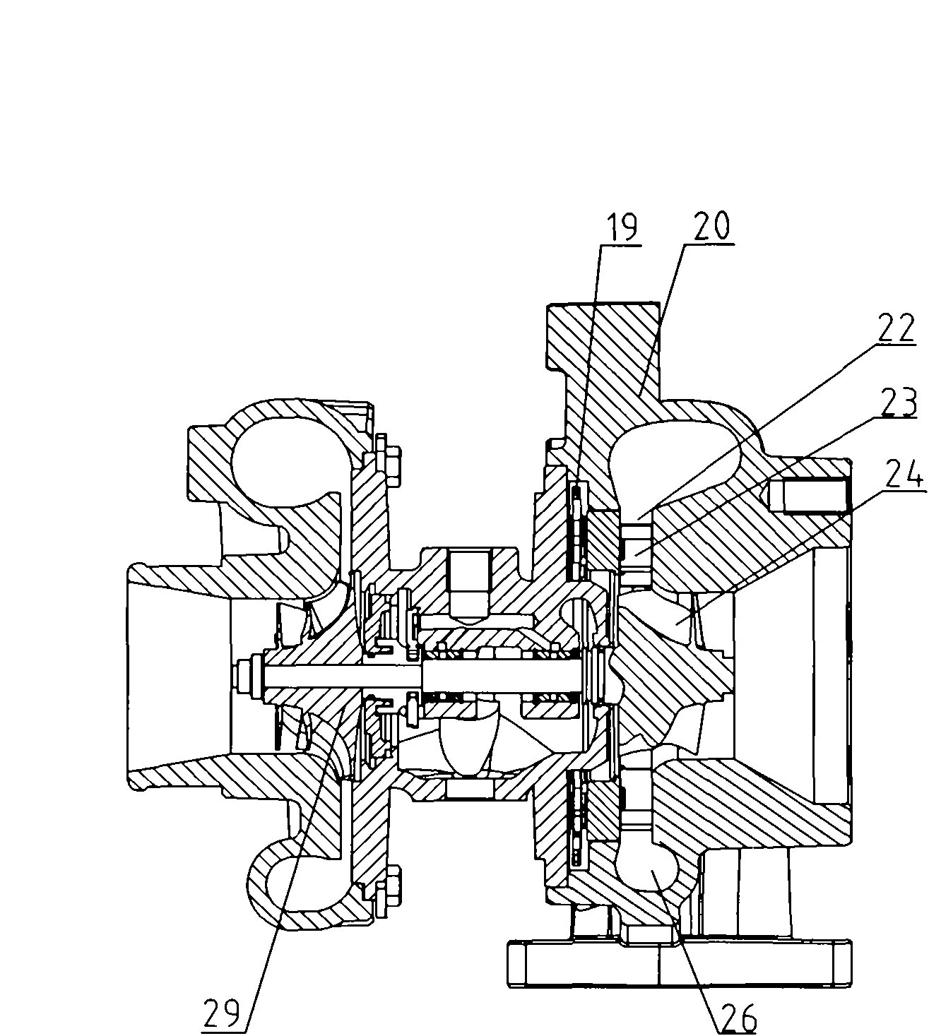
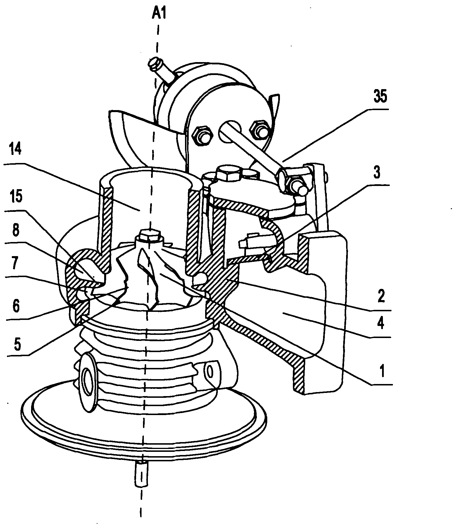
[0057] Embodiment 1, as attached figure 2 As shown, a variable cross-section compound turbine device includes a double-channel turbine volute 2, and the double-channel turbine volute 2 is provided with two airflow passages, and the airflow passage includes a small flow passage 7 and a large flow passage 8 The double-channel turbine volute 2 is provided with a volute air outlet 14 and a volute air inlet 4 communicating with the air flow channel, and a compound turbine wheel 1 is arranged in the double-channel turbine volute 2, and the compound turbine wheel 1 is composed of Two turbine impellers are combined, and the two turbine impellers are matched with two airflow passages one by one. The inlet of the double-channel turbine volute is provided with an airflow regulating valve 3 and a valve control mechanism 35 .

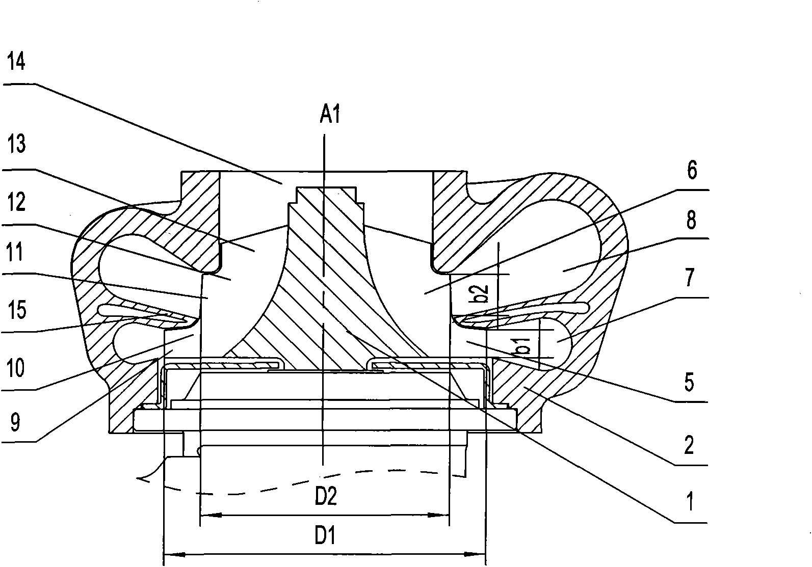
[0058] as attached image 3 As shown, the turbine impeller includes a primary turbine impeller 5 and a secondary turbine impeller 6 , and the primary turbine impe...

Embodiment 2

[0069] Embodiment 2, as attached Figure 6 As shown, the difference between this embodiment and Embodiment 1 is that the positions of the large flow passage 8 and the small flow passage 7 of the double-channel volute 2 are exchanged, and the first-stage turbine impeller 5 and the second-stage turbine wheel 5 of the compound turbine impeller 1 are The 6 positions of the impellers are exchanged. At this time, the large flow channel 8 is located on the side away from the volute air outlet 14, the small flow channel 7 is located on the side close to the volute air outlet 14, the first-stage turbine impeller 5 is located on the side of the wheel rim, and the second-stage turbine wheel 6 is located on the side of the wheel rim. plate side.

[0070] This configuration eliminates flow losses due to disc back clearance, further improving the efficiency of the first stage turbine at low engine speeds. Due to the relatively large diameter D1 of the primary turbine inlet, the double-cha...

Embodiment 3

[0072] Example 3, such as Figure 7 As shown, in the above-mentioned embodiment 1, an airflow guide vane 16 can also be provided at the nozzle of the large flow channel 8 , and the airflow guide vane 16 is obliquely installed at the nozzle of the large flow channel 8 . The airflow guide vane 16 is inclined to the direction of rotation of the turbine to ensure that the airflow enters the turbine at a prescribed angle. Adopting this technical solution can improve the energy utilization efficiency of the exhaust gas at medium and high speeds of the engine, and effectively prevent the backflow generated at the inlet of the secondary turbine from entering the large flow channel 8 at low speeds of the engine.


PUM


Abstract

The invention discloses a complex turbine device with a variable section, comprising a double flow channel turbine volute, wherein the double flow channel turbine volute is provided with two air flow passageways; the double flow channel turbine volute is provided with a volute air outlet and a volute air inlet which are communicated with the air flow passageways; a complex turbine impeller is arranged in the double flow channel turbine volute; and the complex turbine impeller is formed by compounding two turbine impellers which correspond to the two air flow passageways one by one. In the invention, the variable section function can be achieved by design and development of the turbine of a turbocharger and by using the complex turbine device, thereby effectively solving the defects of poor reliability and high cost of a vane type turbocharger with the variable section, effectively improving the efficiency of the turbine of an engine in low speed and increasing the torque output of the turbine.

Description

technical field [0001] The invention relates to a novel turbine device, in particular to a variable cross-section composite turbine device for turbocharging, which can effectively meet the requirements of low-speed and high-speed supercharging of the engine, and belongs to the field of internal combustion engine supercharging. Background technique [0002] With the gradual improvement of emission standards, superchargers are widely used in modern engines. In order to meet the performance and emission requirements under all engine operating conditions, especially low-speed operating conditions, the supercharger must provide higher boost pressure, and has the function of adjusting the intake pressure and exhaust pressure of the engine. Compressors have become the focus of research and development in the field of supercharging. At present, the structure of adding rotatable vanes to the nozzle of the turbine volute is generally used to meet the requirements of variable cross-se...

Claims


Application Information

Patent Timeline
IPC IPC(8): F02B37/24F02B37/22F01D25/24
CPCF01D9/026F01D5/048F02B37/025F05D2300/603F05D2220/40Y02T10/144F02B37/225Y02T10/12
Inventor 朱智富郭晓伟王航李永泰李延昭刘功利杨国强宋丽华
Owner KANGYUE TECH
Why Eureka
Try Eureka