Power output apparatus and hybrid vehicle

a technology of power output apparatus and hybrid vehicle, which is applied in the direction of hybrid vehicle, gearing, electric propulsion mounting, etc., can solve the problems of difficulty in applying the power output apparatus of this structure to a front wheel drive vehicle, and the vehicle is not suitably mounted on the vehicle, so as to improve fuel consumption, improve power transmission efficiency, and facilitate driving performance

Inactive Publication Date: 2011-11-15
TOYOTA JIDOSHA KK
View PDF21 Cites 17 Cited by
  • Summary
  • Abstract
  • Description
  • Claims
  • Application Information

AI Technical Summary

Benefits of technology

[0022]According to another aspect, the invention is also directed to a hybrid vehicle equipped with the power output apparatus having any of the arrangements discussed above and with drive wheels that are driven by power from the driveshaft. The power output apparatus mounted on the hybrid vehicle has the improved power transmission efficiency in the wider driving range as discussed above. The hybrid vehicle with the power output apparatus accordingly has the improved fuel consumption and the favorable driving performance.

Problems solved by technology

In this prior art power output apparatus including the parallel shaft-type transmission, the arrangement of the two motors across multiple drive gears included in the parallel shaft-type transmission undesirably increases the dimension of the power output apparatus in its width direction (that is, the dimension in an axial direction of the parallel shaft-type transmission).
The power output apparatus of this structure occupies a relatively large space and is thus not suitably mounted on a vehicle.
There is thus difficulty in applying the power output apparatus of this structure to a front wheel-drive vehicle.

Method used


Image

  • Power output apparatus and hybrid vehicle
  • Power output apparatus and hybrid vehicle
  • Power output apparatus and hybrid vehicle

Examples


Embodiment Construction

[0037]Some modes of carrying out the invention are described below as preferred embodiments.

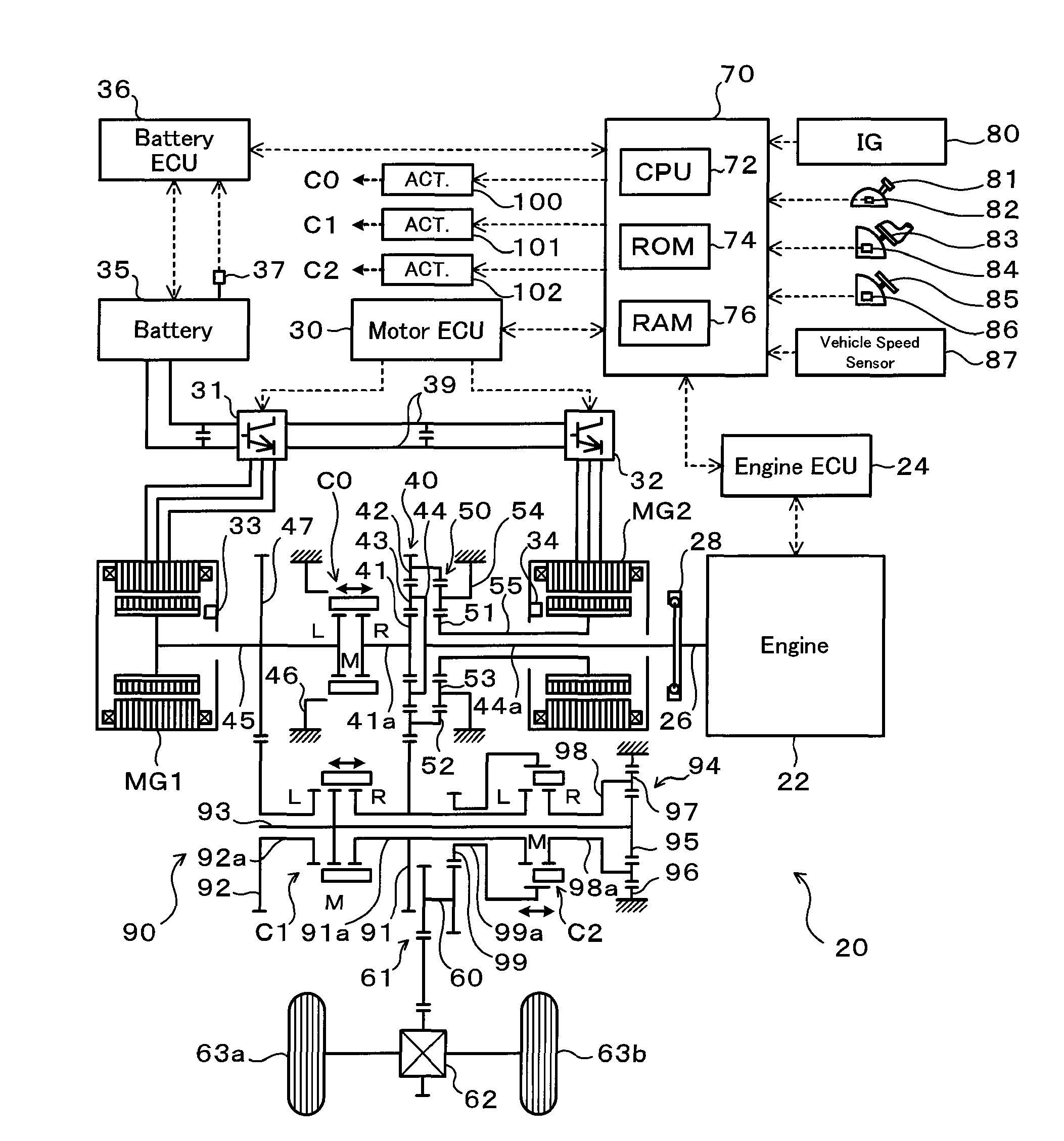
[0038]FIG. 1 schematically illustrates the configuration of a hybrid vehicle 20 in an embodiment of the invention. The hybrid vehicle 20 shown in FIG. 1 is constructed as a front-wheel drive vehicle and includes an engine 22 located in a front portion of the vehicle, a power distribution integration mechanism (differential rotation mechanism) 40 connected with a crankshaft 26 or an output of the engine 22, a motor MG1 arranged coaxially with the crankshaft 26 of the engine 22 and connected with the power distribution integration mechanism 40 and designed to have power generation capability, a motor MG2 arranged coaxially with the engine 22 and the motor MG1 to be connected with the power distribution integration mechanism 40 via a reduction gear mechanism 50 and designed to have power generation capability, a transmission 90 constructed to transmit the output power of the power distribution i...


PUM


Abstract

The hybrid vehicle includes an engine, two motors, and a power distribution integration mechanism arranged coaxially with one another and a transmission. The transmission includes a transmission shaft extended in parallel with a first motor shaft and a second motor shaft, a first coupling gear train in combination with a second coupling gear train and a clutch arranged to selectively connect a ring gear and a sun gear of the power distribution integration mechanism to the transmission shaft, a deceleration mechanism connected with the transmission shaft and arranged to decelerate power from the transmission shaft and output the power of the reduced speed from a carrier, and a clutch arranged to selectively connect the carrier and the ring gear to a driveshaft.

Description

[0001]This is a 371 national phase application of PCT / JP2007 / 070439 filed 19 Oct. 2007, claiming priority to Japanese Patent Application No. JP 2006-288667 filed 24 Oct. 2006, the contents of which are incorporated herein by reference.TECHNICAL FIELD[0002]The present invention relates to a power output apparatus configured to output power to a driveshaft, as well as to a hybrid vehicle equipped with such a power output apparatus.BACKGROUND ART[0003]One proposed structure of the power output apparatus includes an internal combustion engine, two motors, a Ravigneaux planetary gear mechanism, and a parallel shaft-type transmission arranged to selectively connect two output elements of the planetary gear mechanism to an output shaft (see, for example, Patent Document 1). Another proposed structure of the power output apparatus has a planetary gear mechanism including an input element connected with an internal combustion engine and two output elements, and a parallel shaft-type transmis...

Claims


Application Information

Patent Timeline
Patent Type & Authority Patents(United States)
IPC IPC(8): B60K6/44B60K6/48B60K6/46B60L50/16
CPCB60K6/387B60K6/40B60K6/445B60K6/547B60W10/06B60W10/08F16H3/728B60K6/365B60K1/02Y10T477/26B60L2240/486B60W2540/10B60W2540/12B60W2540/16F16H2037/0873F16H2200/0034F16H2200/201F16H2200/2046F16H2200/2064F16H2200/2097Y02T10/6239Y02T10/6286B60L2200/26Y02T10/62
Inventor OBA, HIDEHIROIDESHIO, YUKIHIKO
Owner TOYOTA JIDOSHA KK
Why Eureka
Try Eureka