Eureka AIR delivers breakthrough ideas for toughest innovation challenges, trusted by R&D personnel around the world.

Blank for producing dental shaped parts and method for producing the shaped part

a technology for dental shaped parts and shaped parts, which is applied in the direction of dental articulators, dental prosthetics, tooth crowns, etc., can solve the problems of particularly well recognized tool setup errors, and achieve the effect of ensuring high quality of shaped parts and reducing down times

Active Publication Date: 2011-11-15
SIRONA DENTAL SYSTEMS
View PDF57 Cites 55 Cited by
  • Summary
  • Abstract
  • Description
  • Claims
  • Application Information

AI Technical Summary

Benefits of technology

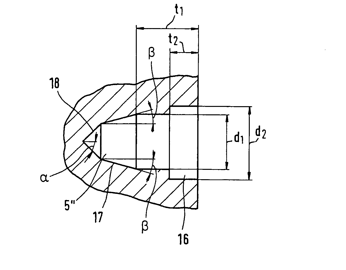
[0012]The gauge is advantageously assigned to an ideal outer contour of a first tool, as this makes it possible to identify the tool that corresponds to the gauge. In addition, another tool having a different ideal outer contour from that of the first tool can be distinguished with the aid of the same gauge. In this way, not only can the tool matching the gauge be selected, but different tools can be distinguished from each other.
[0017]It is especially advantageous when the gauge is designed in such a way that when the tool to which the gauge is assigned is moved into the gauge, the actual state of the permissible allowances of the respective tool can be identified such that the degree of wear of the tool can be assessed and, for example, a certain minimum tool quality can be prescribed. A further advantage is that it is possible to effect a reliable analysis or identification of the tool setup and / or the type of tool used in the machining equipment employed for machining the blank, and the wear condition of said tool.
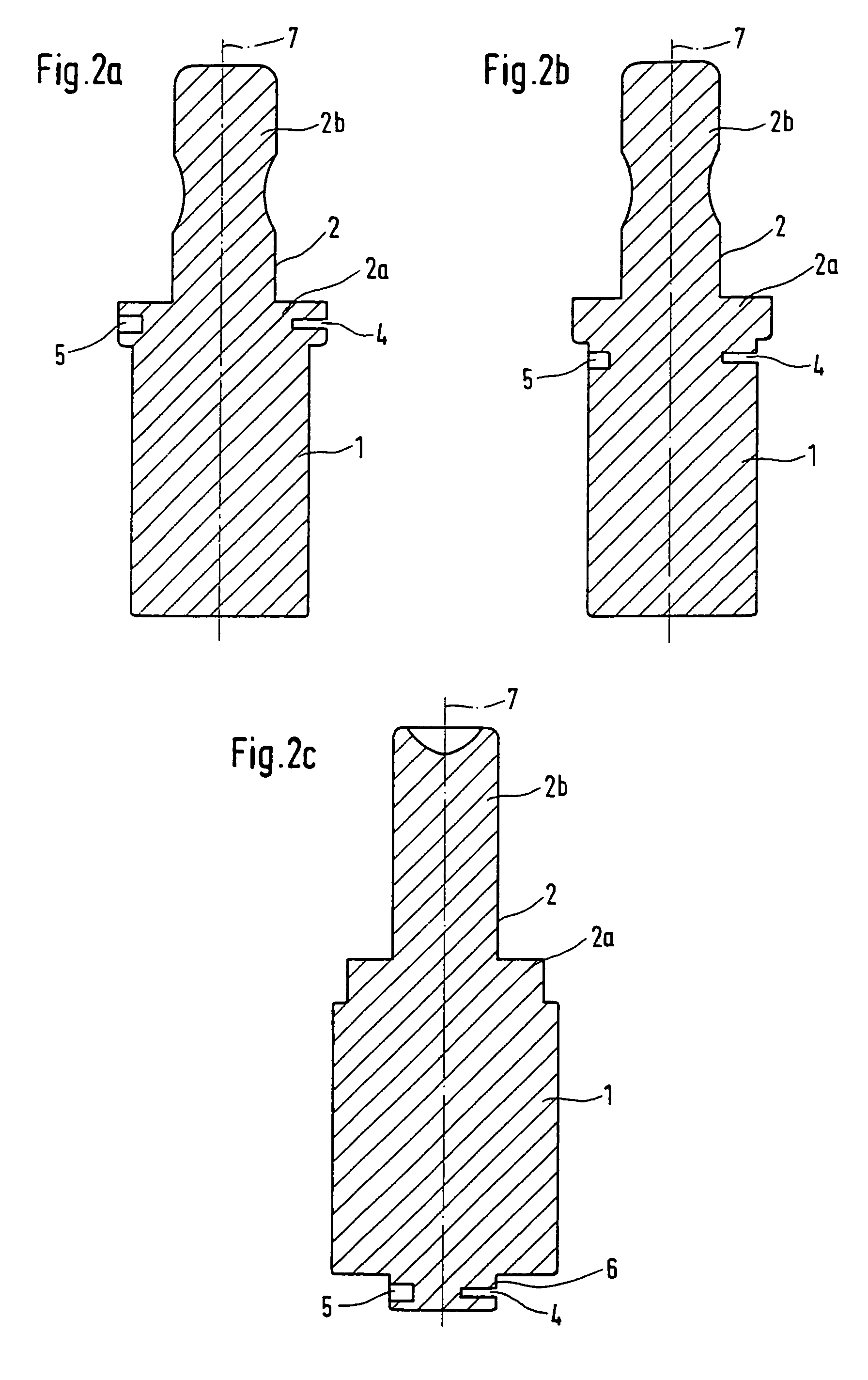
[0018]Another advantage is gained when the blank comprises a handle for mounting and / or positioning the corpus of the blank in a machining device and when the gauge is provided on said handle, since thereby the gauge will remain effective throughout the entire machining operation and the corresponding tools can be checked on a continuous basis. Such identification of poor quality tools or incorrect setups will be contributory, for example, to preventing tool fracture during machining.
[0023]A further advantage results if the tool dedicated to the gauge is driven into the gauge and the current deviation of the assigned tool from the ideal is determined, since information about the momentary tool condition can be determined in this manner each and every time the tool engages the gage(s) gauge(s). This can be done several times during an operation sequence. Thus an optimal condition and, therefore, high quality of the shaped part can be guaranteed.
[0024]Another advantage results when the degree of deviation of the actual condition of the tool from the ideal outer contour of the tool is determined and this deviation is allowed for when organizing the control of the blank machining operation. A parameter, for example, can be established for this purpose. A tool whose unsuitable condition has been recognized can, in such a case, be excluded from the machining process and new or other tools in better condition can carry out the task in hand. It is also conceivable to reduce down times by causing a change of tool to be suggested only if the machining process cannot be finished with any of the other tools that are already involved in the process. The information gained from the comparison can thus be used for a tool condition-specific control of the machining process.

Problems solved by technology

An incorrect tool setup can be particularly well recognized in the case of grinding machines that use different types of tool at the same time.

Method used


Image

  • Blank for producing dental shaped parts and method for producing the shaped part
  • Blank for producing dental shaped parts and method for producing the shaped part
  • Blank for producing dental shaped parts and method for producing the shaped part

Examples


Embodiment Construction

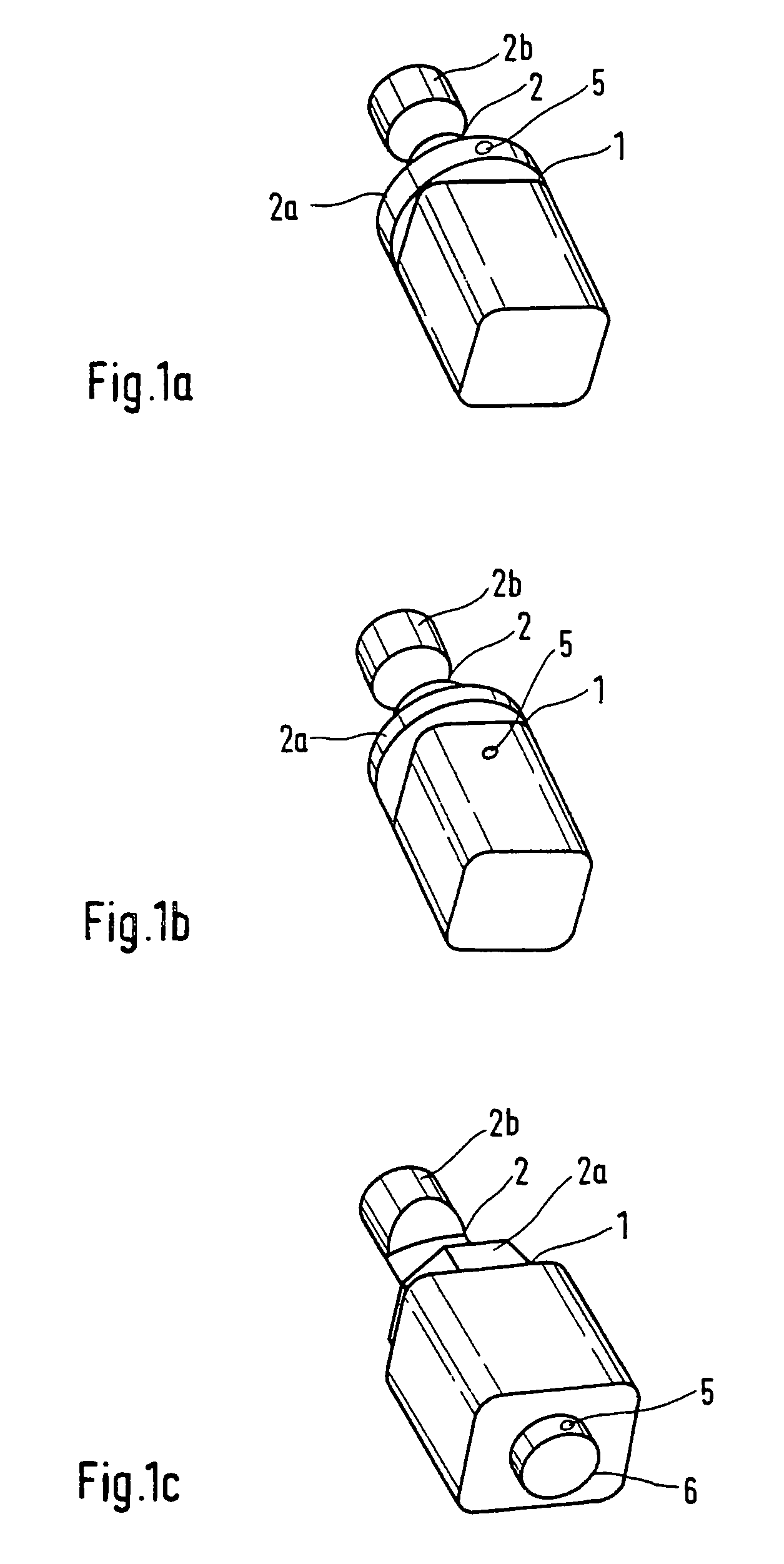
[0049]The blank of FIG. 1a contains a corpus 1, which can consist of a material commonly used in dental technology, e.g., a ceramic material, but also of any other dimensionally stable material such as metal or plastics, from which the shaped part will be fabricated by means of a material removal machining process. The corpus 1 of the blank is advantageously circular or rectangular in cross section. The front end of the corpus of the blank is adjoined by a cylindrical handle 2 in known manner.

[0050]The material of handle 2 can be identical with, or different from, that of the corpus 1. In the case of different materials, blank corpus 1 will be fastened to handle 2, for example by gluing. For this purpose, handle 2 exhibits, for example, a circular cylindrical flange 2a having a diameter that is sufficient to ensure secure attachment to corpus 1, and a shaft 2b for insertion into the machining equipment. Shaft 2b is designed to fit into a predefined socket on the machining equipment....


PUM

PropertyMeasurementUnit
thicknessaaaaaaaaaa
thicknessaaaaaaaaaa
diameteraaaaaaaaaa

Abstract

The invention relates to a blank for producing dental shaped parts, comprising a blank body (1) made of tooth restoration material, from which the shaped part can be machined using a tool (11, 12, 13, 14, 15) for removing material. The aim of the invention is to enable a reliable verification or recognition of the tool fitting or of the type and state of wear of the used tool of a machine tool for the blank. To this end, the blank has at least one gauge (4, 5), whose dimensions are such that the tool present for the machining can be identified by the gauge on the basis of its outer contour. The invention also relates to a method for producing dental shaped parts with a blank body made of tooth restoration material, from which the entire shaped part can be machined in a machining device by a tool for removing material. In order to enable a reliable verification or recognition of the tool fitting or of the type and state of wear of the used tool of a machine tool for the blank, the tool selected for the machining is, before its use, verified with regard to the outer contour thereof by using at least one gauge that is placed upon the blank.

Description

BACKGROUND OF THE INVENTION[0001]1. Field of the Invention[0002]The invention relates to a blank as defined in the claims which is to be used in the production of a dental shaped part, and to a method of producing said shaped part.[0003]2. Description of the Related Art[0004]EP 0 160 797 discloses a blank for the production of dental shaped parts, which blank is made up of a handle and a corpus of different materials. A reference surface on the handle can be formed in such a way that control information for the machining process depending on the characteristics of the blank, can be derived.[0005]Another blank for the production of dental shaped parts is disclosed by DE 196 12 699. Here again, recognition of the type of blank from the geometrical shape of its contours is disclosed.[0006]EP 0 455 854 discloses a blank, from which there can be carved a mating part to be administered to the patient, on the one hand, and an additional retaining or supporting part, on the other hand. A re...

Claims


Application Information

Patent Timeline
Patent Type & Authority Patents(United States)
IPC IPC(8): A61C11/00A61C5/77A61C13/00
CPCA61C13/0003A61C13/0022Y10T29/49567Y10T29/49995Y10T29/49996G05B2219/37227
Inventor BASLER, FRANZFORNOFF, PETER
Owner SIRONA DENTAL SYSTEMS
Why Eureka
Eureka Blog
Learn More