Power tool

a technology of power tools and handles, applied in the field of power tools, can solve the problems of affecting the operation of the operator, and the operator cannot adjust the handle to the desired position relative to the housing,

Active Publication Date: 2011-11-22
MILWAUKEE ELECTRIC TOOL CORP
View PDF176 Cites 12 Cited by
  • Summary
  • Abstract
  • Description
  • Claims
  • Application Information

AI Technical Summary

Benefits of technology

One independent advantage of the present invention is that the handle is movable relative to the housing of the power tool to allow the operator to position the handle as desired for a given cutting operation. As a result, the operator can adjust the handle to a position that is most comfortable and allows the greatest control of the circular saw during cutting operations.
is that the handle is movable relative to the housing of the power tool to allow the operator to position the handle as desired for a given cutting operation. As a result, the operator can adjust the handle to a position that is most comfortable and allows the greatest control of the circular saw during cutting operations.
Another independent advantage of the present invention is that, when the circular saw is adjusted to change the depth of cut of the saw blade, the operator can also adjust the handle to an optimum position for the given cutting operation.
Yet another independent advantage of the present invention is that the circular saw does not include additional components that must be substituted for one another to change the configuration of the handle or additional fasteners. This reduces the chance that such an additional component is lost or damaged and also eliminates the need to store additional components.
A further independent advantage of the present invention is that the handle is adjustable to substantially any position between a first position, such as a “push handle” position, and a second position, such as a “top handle” position.
Other independent features and independent advantages of the invention will become apparent to those skilled in the art upon review of the following detailed description and drawings.

Problems solved by technology

One independent problem with a circular saw including an operator's handle that is integrally formed with the housing, is that, in some cutting operations, the operator may prefer a “push handle” to a “top handle” or vice versa.
However, the operator cannot adjust the handle to the desired position relative to the housing.
Another independent problem with a circular saw with an integral handle is that, when the depth of cut of the saw blade is adjusted, the handle position and orientation also changes.
The resulting handle position is often uncomfortable and is seldom the optimal position for operation of the circular saw.
One independent problem with the handle arrangement disclosed in U.S. Pat. No. 4,516,324 is that the circular saw includes two separate handles.
The handle component that is not in use must be stored and may be lost or damaged.

Method used


Image

  • Power tool
  • Power tool
  • Power tool

Examples


Embodiment Construction

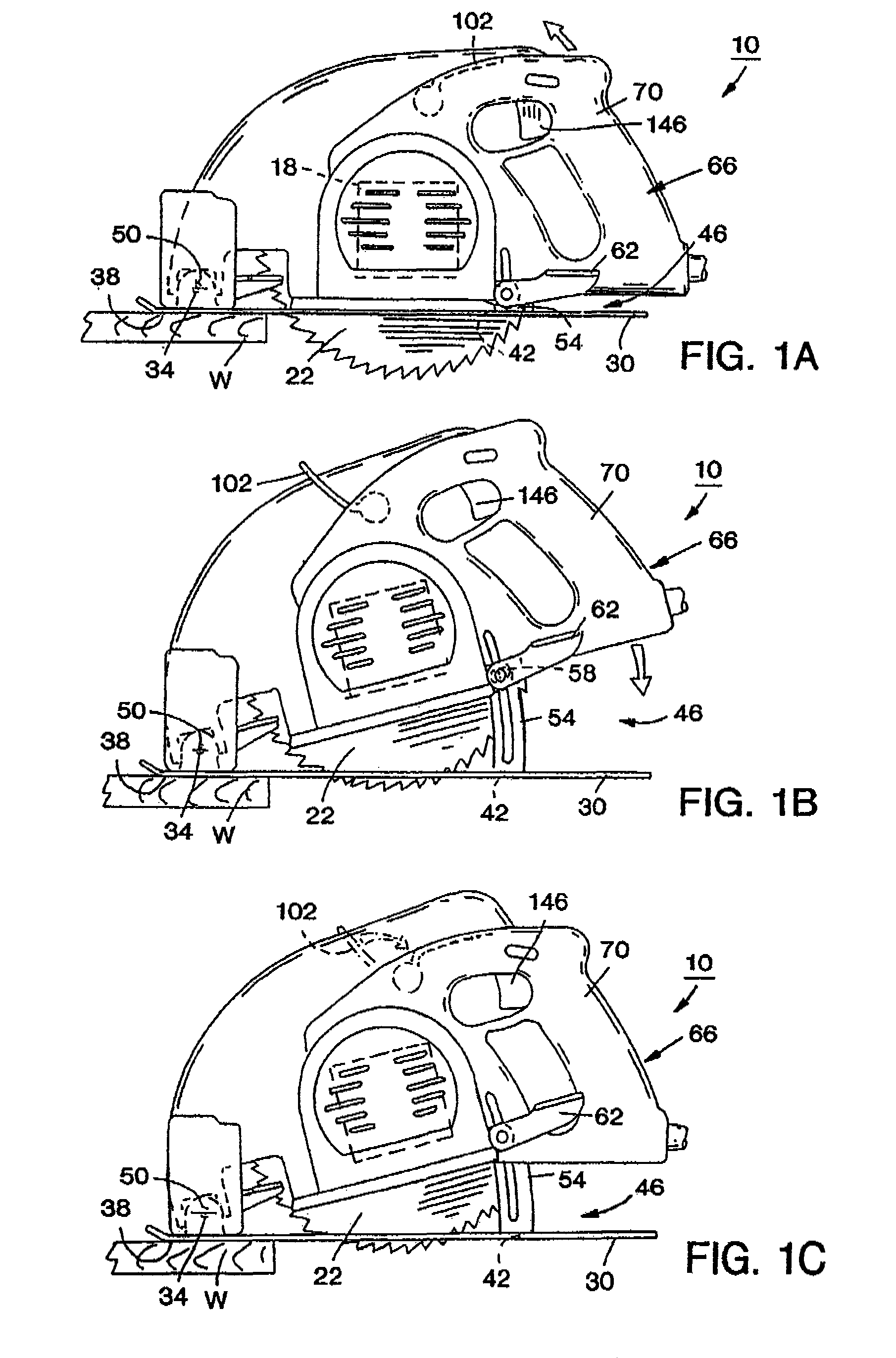
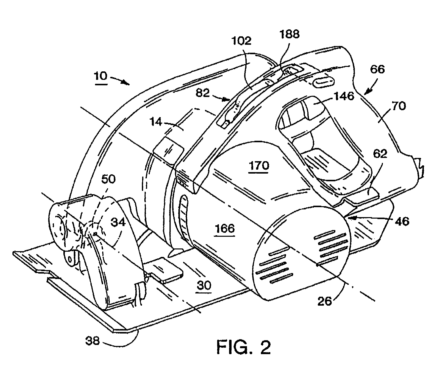
A power tool embodying independent aspects of the invention is illustrated in FIG. 1A. In the illustrated construction, the power tool is a circular saw 10 and includes a motor housing 14 supporting an electric motor 18 (shown schematically in FIG. 1A). The motor 18 is connectable to a power source and is operable to rotatably drive a tool element, such as a saw blade 22, about an axis 26 to cut a workpiece W.

The circular saw 10 also includes (see FIGS. 1A-1C) a shoe plate 30 connected to the housing 14 for pivotal movement about a pivot axis 34. The shoe plate 30 has a support surface 38 for supporting the circular saw 10 on the surface of the workpiece W. An aperture 42 is defined by the shoe plate 30. A portion of the saw blade 22 extends through the aperture 42 to cut the workpiece W. FIG. 1A illustrates the shoe plate 30 adjusted so that the saw blade 22 is at a maximum depth of cut. FIGS. 1B and 1C illustrate the shoe plate 30 adjusted so that the saw blade 22 is at a minimum ...


PUM

PropertyMeasurementUnit
bevel angleaaaaaaaaaa

Abstract

A power tool, a saw and a circular saw. The power tool may include a handle including a support portion movably supportable on the housing portion and extending substantially about the circumference of the housing portion. The support portion may include a second end movable relative to a first end such that the support portion selectively applies a force to the housing portion. The saw may include a bevel angle detent mechanism in which one of the detent member and the recess is angularly adjustable relative to the associated one of the detent support and the recess support to adjust the predetermined bevel angle position. A bevel angle detent mechanism may include an engagement operating assembly operable between a detent engagement-enabled condition, in which the detent member is engageable in the recess, and a detent engagement-prevention condition, in which the detent member is prevented from engaging the recess. The circular saw may include a spindle lock assembly.

Description

FIELD OF THE INVENTIONThe present invention relates to power tools and, in some independent aspects, to a handle arrangement for power tools.SUMMARYOne independent problem with a circular saw including an operator's handle that is integrally formed with the housing, is that, in some cutting operations, the operator may prefer a “push handle” to a “top handle” or vice versa. However, the operator cannot adjust the handle to the desired position relative to the housing.Another independent problem with a circular saw with an integral handle is that, when the depth of cut of the saw blade is adjusted, the handle position and orientation also changes. The resulting handle position is often uncomfortable and is seldom the optimal position for operation of the circular saw.For example, in a circular saw with a front pivot depth adjustment assembly, at full depth of cut, the handle is typically positioned as a “push handle”. At a minimum depth of cut, the handle position is changed to a “to...

Claims


Application Information

Patent Timeline
Patent Type & Authority Patents(United States)
IPC IPC(8): B23D45/16
CPCB27B9/02
Inventor ALLEN, DOUGLAS W.FISCHER, SCOTT R.BANACH, PETER A.BERG, STEVEN L.
Owner MILWAUKEE ELECTRIC TOOL CORP
Why Eureka
Try Eureka