Retrofit framing system for metal roof

a technology of metal roofs and support assemblies, which is applied in the direction of building roofs, building repairs, doors/windows, etc., can solve the problems of degrading and eventually destroying typical roofs in high wind weather conditions, affecting and affecting the weather resistance of buildings. , to achieve the effect of significantly increasing the wind resistance of building roofs

Active Publication Date: 2011-11-22
RAY GINO
View PDF21 Cites 20 Cited by
  • Summary
  • Abstract
  • Description
  • Claims
  • Application Information

AI Technical Summary

Benefits of technology

[0006]It is another object of the invention to provide a retrofitting assembly designed to increase wind resistance of the roof.
[0007]It is a further object of the invention to provide a retrofitting assembly for reinforcing the roof structure that can be installed on top of the existing roof panels without the need to replace the roof.
[0008]It is still a further object of the invention to provide a retrofitting assembly that can be installed over an existing roof and bring the roof into compliance with current building codes without the need to remove the existing roof or to add new framing members to meet new wind load requirements (code).
[0011]The new support assembly provides considerable larger number of attachment points for the new roof, particularly along the peripheral roof line. As a result, wind pressure resistance of the building roof is significantly increased.

Problems solved by technology

The typical roof in a high wind weather condition is degraded and eventually destroyed because one or more roofing panels and / or the ridge caps are lifted off of the structure.
When this happens, the entire roof is quickly peeled off of the building and the rest of the building is exposed to the weather.
Older roofs, especially those constructed according to the earlier building codes, are particularly susceptible to wind pressure because there are not enough points of attachment of the roof panels to the underlying roof support structure, such as a plywood deck, rafters or purlins.
In the geographic areas where hurricanes happen every year, the screw-down preformed metal roofs often fail, when high velocity winds rip off the roof from the building.

Method used


Image

  • Retrofit framing system for metal roof
  • Retrofit framing system for metal roof
  • Retrofit framing system for metal roof

Examples


Embodiment Construction

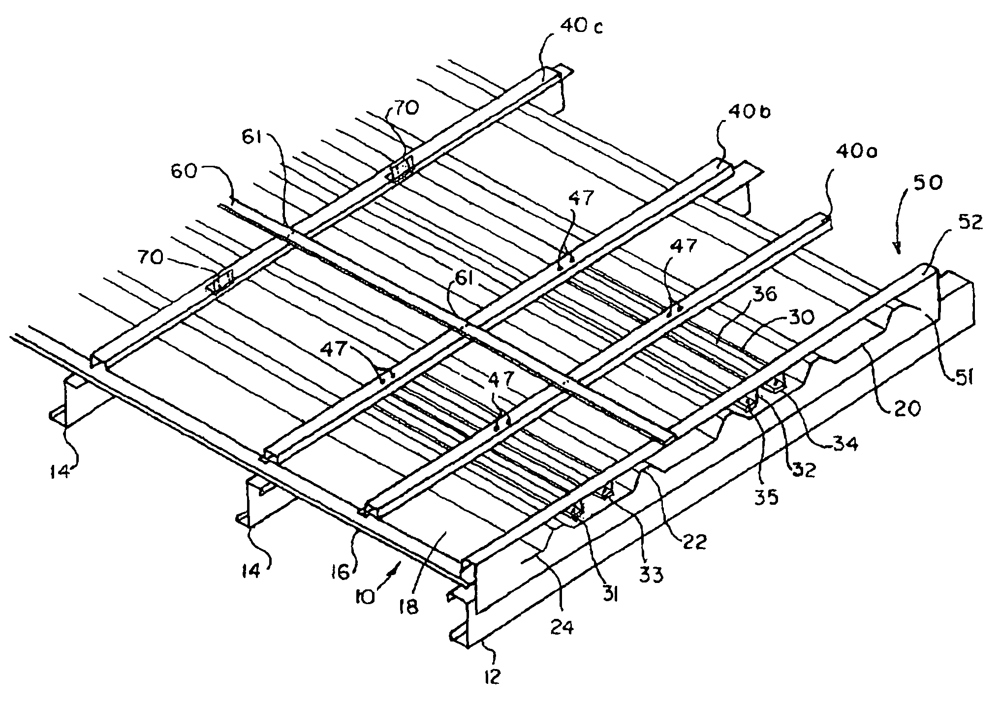
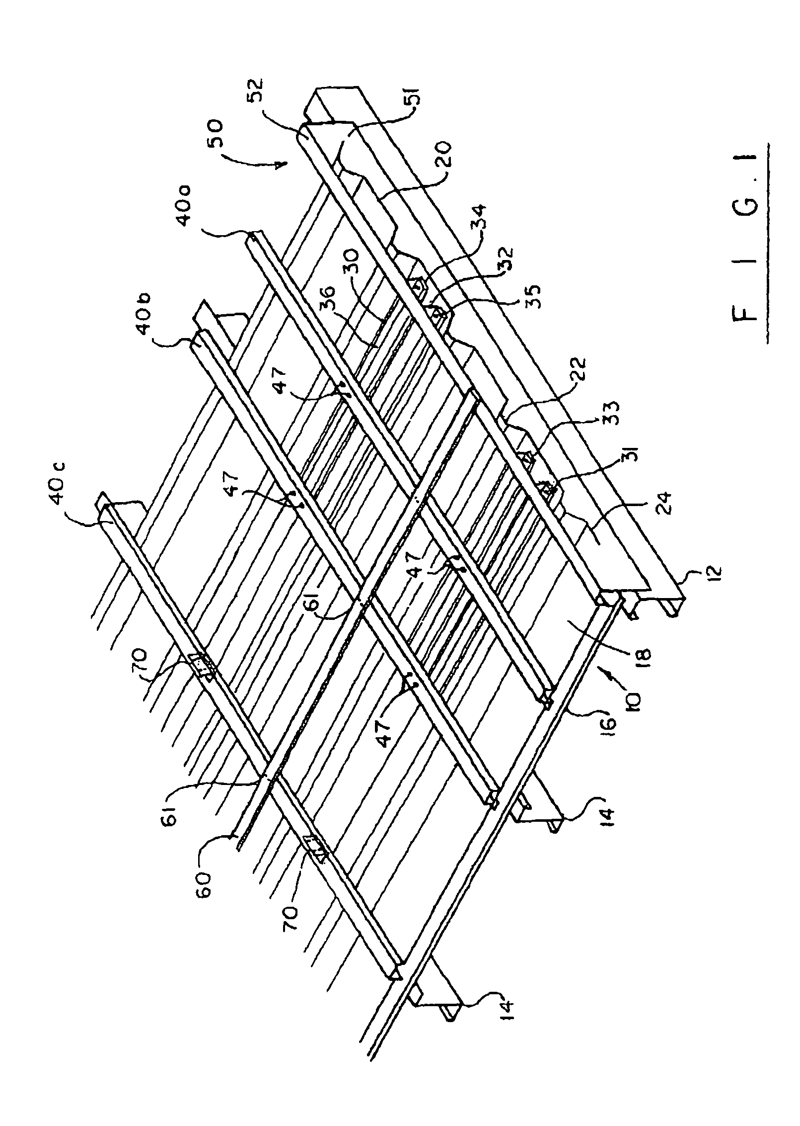
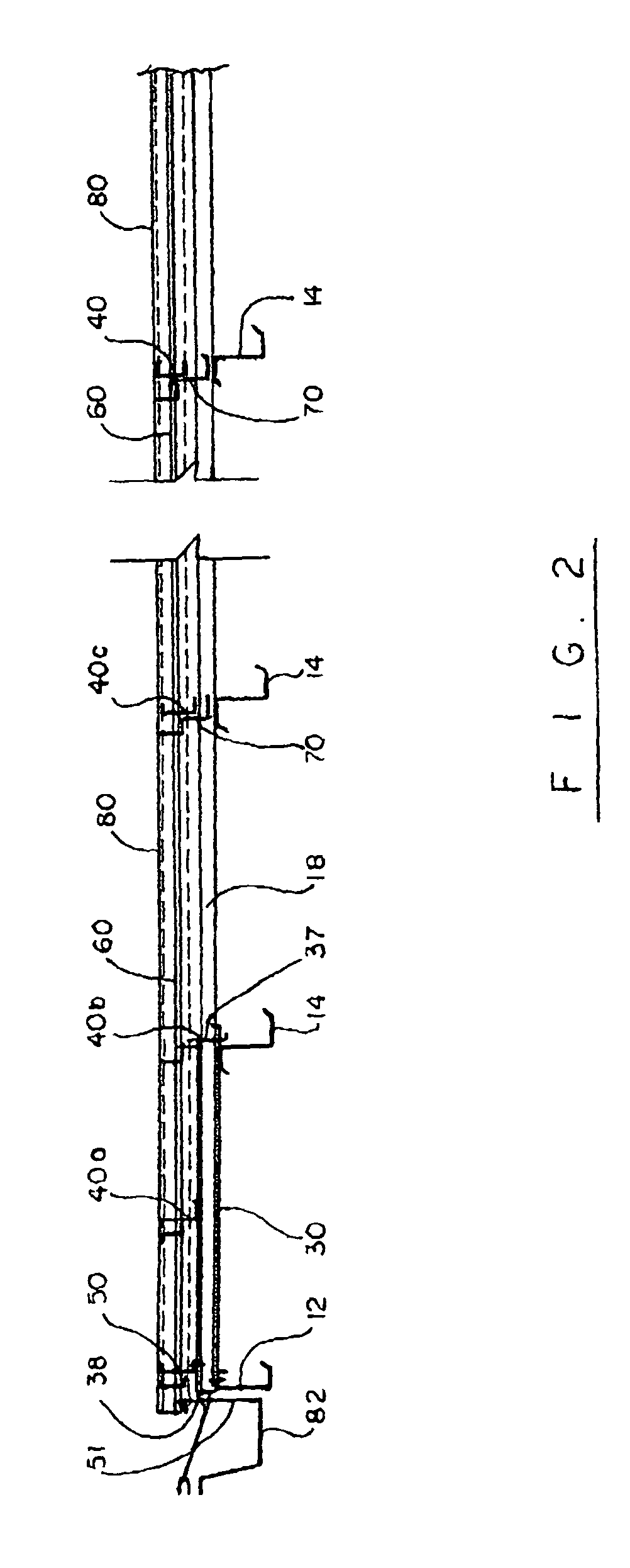
[0024]Turning now to the drawings in more detail, numeral 10 designates an existing roof made of preformed metal panels 18. The roof illustrated in the drawings is a standard R-panel roof, which is typically made of galvanized steel. Another frequently used alternative in roof panels is the so-called standing seam roof. An eave strut 12 forms the edge of the roof supporting structure and somewhat projects beyond the side of the building in some cases.

[0025]A plurality of purlins 14 extends in a generally parallel relationship to the roof edge; the purlins 14 support the loads from the roof deck or sheathing 16. The purlins 14 are supported by the principal rafters and / or the building walls (not shown). As can be seen in the drawings, conventional purlins 14 are formed of Z-shaped sections; they can be formed of cold-formed steel. The purlins 14 are spaced from each other by about 4 feet or more. The roof panels 18 are corrugated, with high ridges 22 alternating with drain channels 2...


PUM


Abstract

A support assembly for supporting a retrofit roof to be installed above an existing roof made of preformed panels. Elongated support assembly members are positioned along the roof line to provide additional points of attachment for the new roof, while at the same time forming a substantially even plane for new rood panels. Some of the support members fit in the channels between the ridges of the preformed panels, which can be R-panels or standing seam panels. Transverse top members secure the channel-mounted members in place, while strapping members positioned atop the top members form additional lateral support for the new roof.

Description

BACKGROUND OF THE INVENTION[0001]This invention relates to roofing systems, and, more particularly to a support assembly for retrofitting a roof made of preformed panels in order to improve wind pressure resistance of a new roof.[0002]The typical roof in a high wind weather condition is degraded and eventually destroyed because one or more roofing panels and / or the ridge caps are lifted off of the structure. When this happens, the entire roof is quickly peeled off of the building and the rest of the building is exposed to the weather. Older roofs, especially those constructed according to the earlier building codes, are particularly susceptible to wind pressure because there are not enough points of attachment of the roof panels to the underlying roof support structure, such as a plywood deck, rafters or purlins.[0003]Rapid changes in the roofing systems bring new concepts to the roofing material development. For instance, preformed metal panels may replace standing seam roof or vic...

Claims


Application Information

Patent Timeline
Patent Type & Authority Patents(United States)
IPC IPC(8): E04B7/02
CPCE04D3/3608E04G23/0281
Inventor RAY, GINO
Owner RAY GINO
Why Eureka
Try Eureka