Combination devices clamp spring designed with devices cage

a technology of devices and clamp springs, which is applied in the direction of instruments, furniture parts, electrical apparatus casings/cabinets/drawers, etc., can solve the problems of cage rattle, cage rattling, and insufficient clamping force or friction of the contact springs of the securing plates to prevent drives within the cage from vibrating, etc., to limit the rattling noise of the devices cage, maintain the rigidity of the wall, and limit the rattling nois

Active Publication Date: 2011-11-22
MYPAQ HLDG LTD
View PDF68 Cites 12 Cited by
  • Summary
  • Abstract
  • Description
  • Claims
  • Application Information

AI Technical Summary

Benefits of technology

[0009]In a further aspect, a wall of a chassis comprises at least one elongated opening across a length of the wall and at least one bridge positioned across the at least one elongated opening. In some embodiments, each end of the at least one elongated opening extends at an inwards slant toward a center of the wall. The inwards slant terminates at a circular area around, which is configured in a dome shape with a flat top. Typically, the circular area controls dispersion of force. Preferably, the at least one bridge is configured to maintain rigidity of the wall. The at least one bridge protrudes outwards away from the wall. In other embodiments, the wall further comprises a plurality of clamp springs integrally coupled to a top of the at least one elongated opening. Each of the plurality of one clamp springs comprises a tongue and a clamp. A first part of the tongue extends outwards away from the wall and a second part of the tongue parallels the wall. The second part of the tongue is projected and positioned over a portion of the at least one elongated opening. The clamp is also projected and positioned over a portion of the at least one elongated opening. The clamp comprises an angled end and a flat end. The flat end parallels the wall and an angled end angles away from the wall. The flat end positions over a drive mounting screw. In some embodiments, the clamp has a clamping force of 1.5 kgf. Preferably, the clamping force is configured to prevent a device from vibrating. The clamping force is configured to limit rattling noises of the chassis. As such, the plurality of clamp springs has a friction damper characteristic.

Problems solved by technology

For example, contact springs of the securing plates do not provide enough clamping force or friction to prevent drives within a cage from vibrating.
As such, when the drives vibrate within the cage, the cage rattles, creating disturbing and often loud noises.
In addition, since the securing plates are separate components from the cage, use of the securing plates is an extra cost.
Furthermore, the securing plates can be lost or misplaced.

Method used


Image

  • Combination devices clamp spring designed with devices cage
  • Combination devices clamp spring designed with devices cage
  • Combination devices clamp spring designed with devices cage

Examples


Embodiment Construction

[0021]In the following description, numerous details are set forth for purposes of explanation. However, one of ordinary skill in the art will realize that the invention may be practiced without the use of these specific details. Thus, the present invention is not intended to be limited to the embodiments shown but is to be accorded the widest scope consistent with the principles and features described herein.

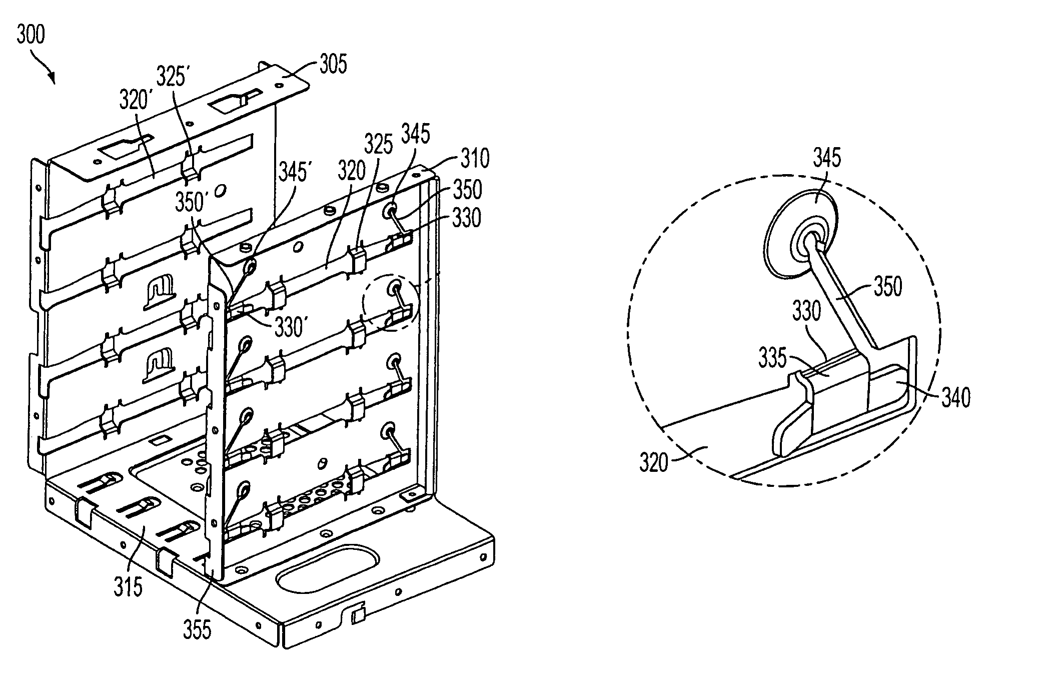
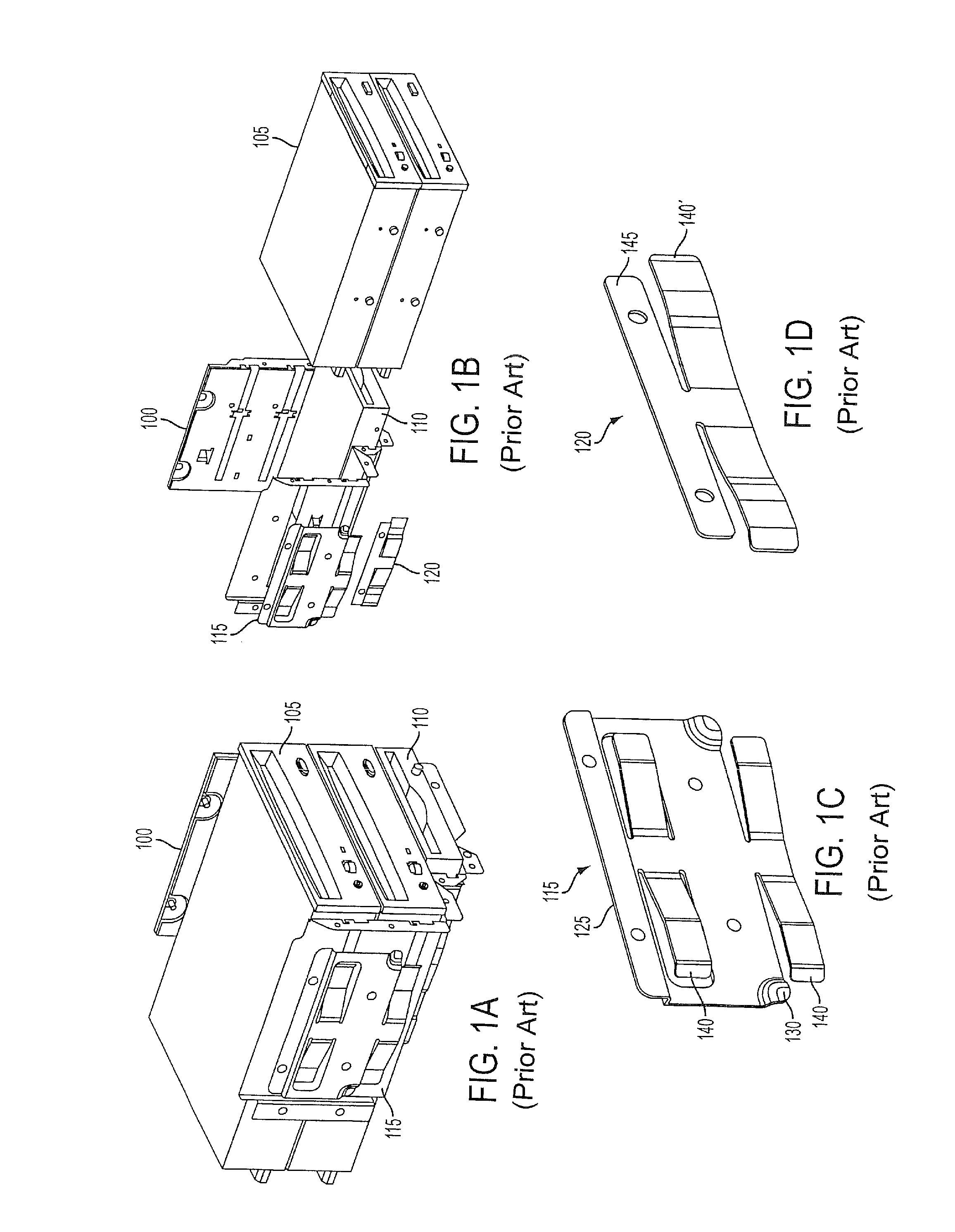
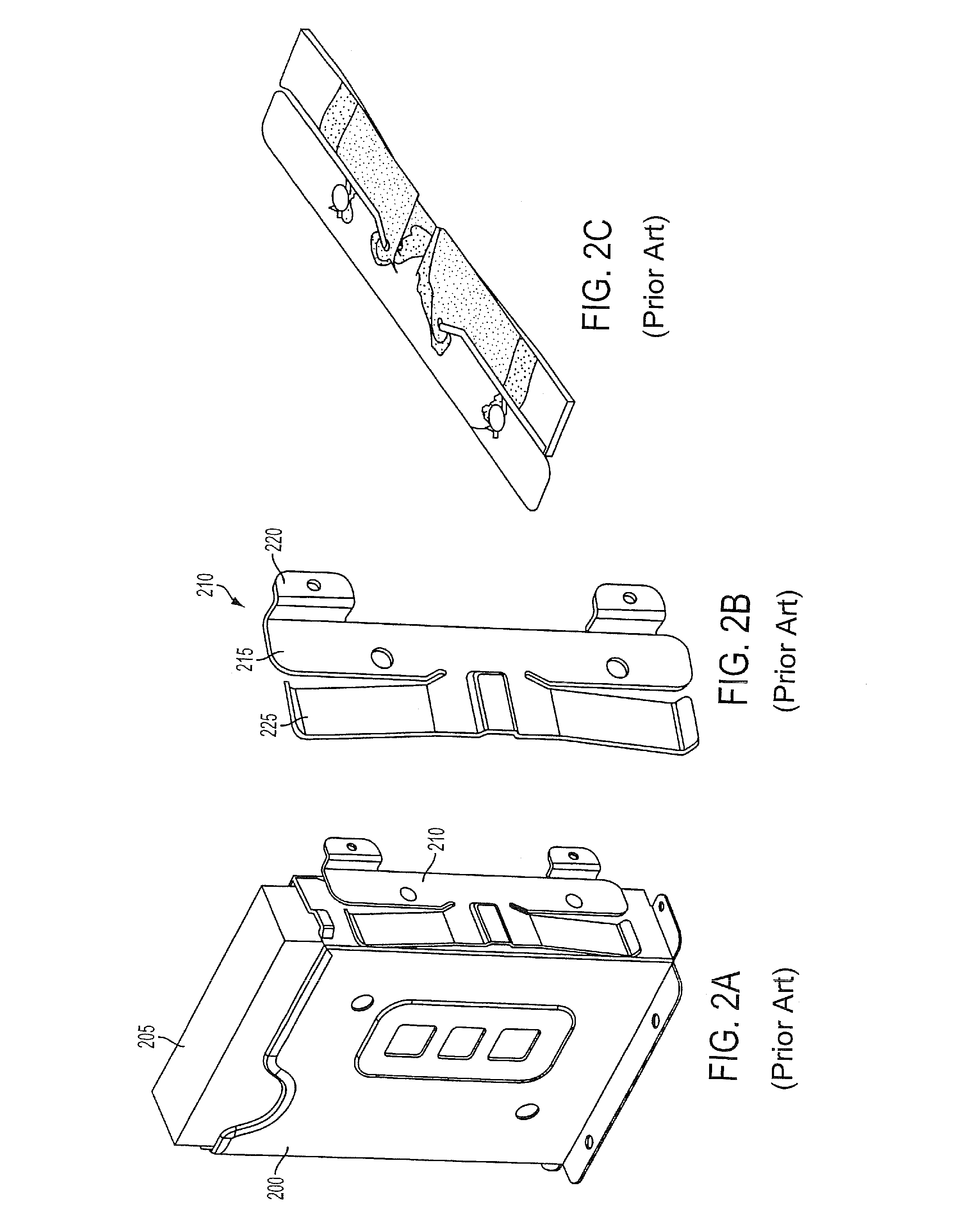
[0022]A traditional m-unit cage for holding together m drives within the m-unit cage includes using separate components, specifically securing plates, to prevent the drives from vibrating and thus rattling the cage. Unlike the traditional m-unit cage, embodiments of the present invention are to provide a combination devices clamp spring designed with a devices cage to hold together the m drives within the devices cage. Accordingly, the securing plates are no longer necessary and / or used to prevent the m devices within the devices cage from vibrating. Preferably, the m drives in...


PUM


Abstract

A devices cage comprises a first wall having m parallel channels across a length of the first wall and a second wall having n parallel channels across a length of the second wall. In some embodiments, n is at least equal to m. Each parallel channel is equal to a diameter of a head of a drive mounting screw. The first wall comprises at least one bridge positioned across each m parallel channel and at least one clamp spring integrally coupled to a top of each m parallel channel. The second wall also comprises at least one bridge positioned across each n parallel channel. Each end of the m parallel channel extends at an inwards slant toward a center of the first wall. The inwards slant terminates at a circular area around configured in a dome shape with a flat top.

Description

CROSS REFERENCE TO RELATED APPLICATIONS[0001]The application claims priority of U.S. provisional application, Ser. No. 60 / 921,220, filed Mar. 29, 2007, and entitled “Primary Only Constant Voltage / Constant Current (CVCC) Control in Quasi Resonant Converter.” This application incorporates U.S. provisional application, Ser. No. 60 / 921,220, in its entirety by reference.FIELD OF THE INVENTION[0002]The present invention relates to device clamps. More particularly, the present invention relates to the combination devices clamp spring designed with a devices cage.BACKGROUND OF THE INVENTION[0003]An m-unit cage is used to hold together m drives such as optical disk drives (ODDs), floppy disk drives (FDDs), hard disk drives (HDDs), and other drives. Separate securing plates and a plurality of screws are used to fasten the drives to the m-unit cage. For example, FIGS. 1A-1B illustrate a three-unit cage 100 for holding together two ODDs 105 and one FDD 110. The two ODDs 105 are positioned above...

Claims


Application Information

Patent Timeline
Patent Type & Authority Patents(United States)
IPC IPC(8): A47F7/00
CPCG11B33/127
Inventor CHENG-YUAN, FANCHIN, SAM
Owner MYPAQ HLDG LTD
Why Eureka
Try Eureka