Frequency synthesizer circuit comprising a phase locked loop

a phase lock and loop technology, applied in the field of frequency synthesizer circuits, can solve the problems of insufficient non-linear signal processing and limited effect of real-world plls, and achieve the effect of increasing the tolerance to non-linear distortion and the limit cycl

Active Publication Date: 2011-03-22
STMICROELECTRONICS DESIGN & APPL
View PDF6 Cites 15 Cited by
  • Summary
  • Abstract
  • Description
  • Claims
  • Application Information

AI Technical Summary

Benefits of technology

[0014]In accordance with one aspect of the present disclosure, a frequency synthesizer circuit is provided that includes a phase locked loop circuit having at least a phase detector, a controlled oscillator for generating a local frequency signal, and a frequency divider coupled to the controlled oscillator and having a control input for adjusting a frequency division of the frequency divider in response to a received control signal generated from a divisor value. The frequency synthesizer circuit further includes a dithering circuit for providing a dither signal, and a sigma-delta modulator comprising an input for receiving a multi-bit input signal indicative of at least part of the divisor value and an output coupled to the control input of the frequency divider. The input of the sigma-delta modulator is coupled with the dithering circuit for receiving the dither signal as a most significant bit (MSB) of the multi-bit input signal. Accordingly, both, limit cycles and tolerance to non-linear distortion can be increased without increasing the quantization noise. The influence of the pseudo-random dither signal at the most significant bit of the sigma-delta modulator is greater than a dither signal applied as least significant bit, as applied in the prior approach according to FIG. 1.
[0016]According to a further aspect, a subtraction circuit having a first input is coupled to the output of the sigma-delta modulator for receiving a first input signal, and which also has a second input coupled to the dithering circuit for receiving the dither signal. The subtraction circuit is adapted for subtracting the dither signal from the first input signal. In a further aspect, a delay circuit is coupled between the subtraction circuit and the dithering circuit for delaying the dither signal and providing a delayed dither signal to the subtraction circuit. Particularly, the delay of the dither signal corresponds to (e.g., is approximately equal to) a signal propagation delay within the sigma-delta modulator. Accordingly, a delayed version of the dither signal is subtracted from the output signal of the sigma-delta modulator. Choosing a proper n-clock delay which compensates the propagation delay from the input node to the output node at the sigma-delta modulator eliminates the dither signal from the modulator output.

Problems solved by technology

While this is sufficient if the quantization noise is subject to strictly linear signal processing, it is not sufficient in case of non-linear signal processing.
Although good results can be achieved with these methods in idealized simulations with solely linear PLL building blocks, in real-world PLLs their effectiveness is very limited due to insufficient tolerance of the quantization noise to non-linear distortion.

Method used


Image

  • Frequency synthesizer circuit comprising a phase locked loop
  • Frequency synthesizer circuit comprising a phase locked loop
  • Frequency synthesizer circuit comprising a phase locked loop

Examples


Embodiment Construction

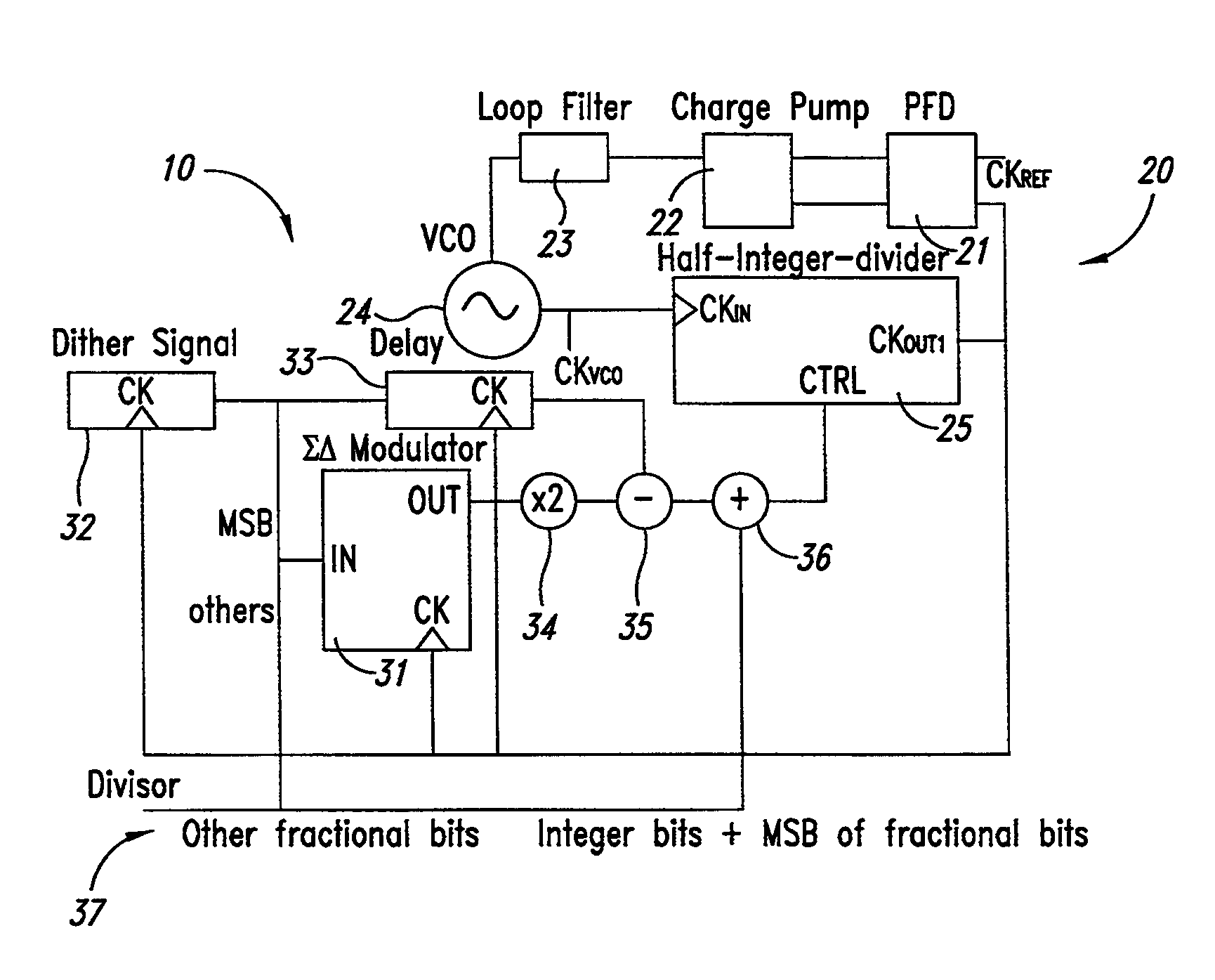
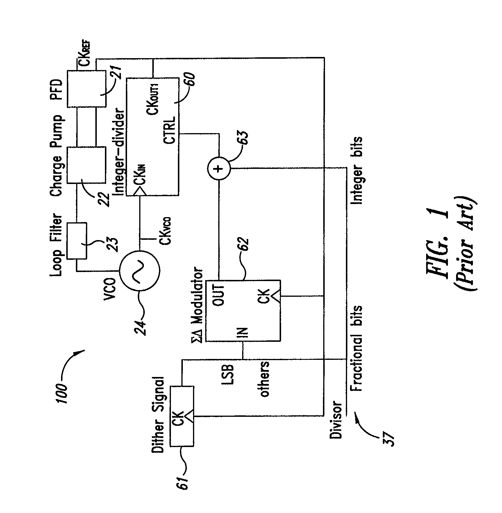
[0027]FIG. 3 shows a block diagram depicting an exemplary frequency synthesizer circuit that implements a sigma-delta PLL according to an embodiment of the present disclosure. The frequency synthesizer circuit 10 includes a phase locked loop circuit 20 which includes a phase-frequency detector 21, a charge pump 22, a loop filter 23, and a voltage controlled oscillator (VCO) 24. With respect to these components, it is also referred to the above description with regard to FIG. 1 in which the same or equivalent components are used. As a difference to the circuit of FIG. 1, the frequency synthesizer circuit 10 according to FIG. 3 implements a half-integer-divider as a frequency divider 25 that is coupled to the controlled oscillator 24. The frequency divider 25 has a control input CTRL for adjusting a frequency division of the frequency divider 25 in response to a received control signal at the control input CTRL which is generated from a divisor value 37, as set out in more detail belo...


PUM


Abstract

A frequency synthesizer circuit that reduces undesired spurious sidebands while maintaining phase noise performance having a phase locked loop circuit comprising at least a phase detector, a controlled oscillator, a frequency divider coupled to the controlled oscillator for adjusting a frequency division of the frequency divider in response to a received control signal generated from a divisor value, a dithering circuit for providing a dither signal, and a sigma-delta modulator comprising an input for receiving a multi-bit input signal indicative of at least part of the divisor value. The input of the sigma-delta modulator is coupled with the dithering circuit for receiving the dither signal as a most significant bit of the multi-bit input signal.

Description

BACKGROUND[0001]1. Technical Field[0002]The present disclosure pertains to a frequency synthesizer circuit and, more particularly, to a frequency synthesizer circuit having a phase locked loop circuit that reduces undesired spurious sidebands while maintaining phase noise performance.[0003]2. Description of the Related Art[0004]Frequency synthesizers may be employed in communication or entertainment applications such as in receivers for radio frequency tuners for receiving and tuning broadcasting signals. A frequency synthesizer of such system may include a phase locked loop (PLL) comprising a controlled oscillator, such as a voltage controlled oscillator, a loop filter, and a phase-frequency detector. Further, a frequency divider may be coupled to the controlled oscillator for dividing down the frequency of the controlled oscillator output signal. In such frequency divider, the frequency division may be adjusted in response to a control signal at the frequency divider which is indi...

Claims


Application Information

Patent Timeline
Patent Type & Authority Patents(United States)
IPC IPC(8): H03B21/00
CPCH03L7/1976
Inventor ZELLER, SEBASTIAN
Owner STMICROELECTRONICS DESIGN & APPL
Why Eureka
Try Eureka