Lens focal plane array heterodyne reception optical antenna of synthetic aperture laser imaging radar

A technology of synthetic aperture laser and imaging radar, which can be used in the re-radiation of electromagnetic waves, radio wave measurement systems, instruments, etc., and can solve problems such as difficulties in engineering implementation.

Inactive Publication Date: 2010-01-20
SHANGHAI INST OF OPTICS & FINE MECHANICS CHINESE ACAD OF SCI
View PDF0 Cites 15 Cited by
  • Summary
  • Abstract
  • Description
  • Claims
  • Application Information

AI Technical Summary

Problems solved by technology

For synthetic aperture laser imaging radar, someone in the United States proposed an improved scheme (Reference 1), which uses an array detector to realize multi-channel reception of the echo signal of a large-area optical system, and performs target imaging unit for the output of the array detector. The tracking of the phase history, but this method is very difficult to implement in engineering

Method used


Image

  • Lens focal plane array heterodyne reception optical antenna of synthetic aperture laser imaging radar
  • Lens focal plane array heterodyne reception optical antenna of synthetic aperture laser imaging radar
  • Lens focal plane array heterodyne reception optical antenna of synthetic aperture laser imaging radar

Examples


Embodiment Construction

[0097] Below in conjunction with accompanying drawing and embodiment, the present invention is described in further detail:

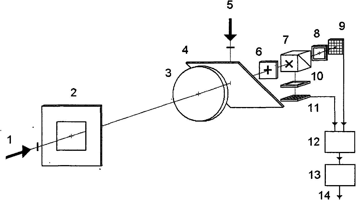
[0098] see first figure 1 , figure 1 It is a schematic diagram of the heterodyne receiving optical antenna of the lens focal plane array of the synthetic aperture laser imaging radar of the present invention. figure 1It is also a system schematic diagram of an embodiment of the present invention. As can be seen from the figure, the lens focal plane array heterodyne receiving optical antenna of the synthetic aperture laser imaging radar of the present invention is composed of the receiving aperture diaphragm 2, the receiving lens 3, the polarization beam combiner 4, and the local oscillator beam in order from the target echo 1. 5. Wave plate 6, polarization beam splitter 7, first detection aperture 8 and first photodetection array 9, second detection aperture 10 and second photodetection array 11, balanced receiving array circuit 12, adder circuit 13 ...


PUM


Abstract

A lens focal plane array heterodyne reception optical antenna of a synthetic aperture laser imaging radar is composed of a reception aperture diagram, a reception lens, a polarization beam combination lens, a local oscillator beam, a wave plate, a polarization beam division lens, two detection diagrams, two photoelectric detection arrays, a balance reception array circuit and a summator circuit; the aperture diagram is positioned on the front focal plane of the reception lens; the photoelectric detection arrays are positioned on the back focal plane of the reception lens; the balance reception array circuit carries out balance reception treatment on the output electronic signals of the two photoelectric detection arrays; the summator circuit carries out linear addition on the array output electronic signals of the balance reception array circuit. The invention can realize a receiving field of view much larger than that of heterodyne decided by the optical antenna caliber diffraction and the caliber a lot larger than that of a transmission optical antenna, can be combined with a transmission optical telescope with relatively smaller caliber to be a co-axial synthetic aperture laser imaging radar optical antenna system.

Description

technical field [0001] The invention relates to a synthetic aperture laser imaging radar, which is a heterodyne receiving optical antenna of a lens focal plane array of the synthetic aperture laser imaging radar, which can realize a receiving field of view much larger than the heterodyne receiving field of view determined by the diffraction of the optical antenna aperture. , and can greatly limit the noise to ensure the received signal-to-noise ratio of the target echo, so its aperture can be much larger than that of the transmitting optical antenna, and it is also easy to combine with the relatively small-diameter transmitting optical telescope antenna into a same structure. Axis synthetic aperture lidar imaging radar optical antenna system. Background technique [0002] The principle of synthetic aperture laser imaging radar (SAIL) is taken from the principle of synthetic aperture radar in the radio frequency field, and it is the only optical imaging observation method tha...

Claims


Application Information

Patent Timeline
Patent Type & Authority Applications(China)
IPC IPC(8): G01S7/481G01S17/89
Inventor 刘立人
Owner SHANGHAI INST OF OPTICS & FINE MECHANICS CHINESE ACAD OF SCI
Why Eureka
Try Eureka