Rig mat system using panels of composite material

a composite material and mat technology, applied in the direction of stairs, building components, stairway-like structures, etc., can solve the problems of unsuitable arrangement, and achieve the effect of providing the required strength characteristics

Active Publication Date: 2011-11-22
RHINOKORE COMPOSITES SOLUTIONS LP
View PDF22 Cites 56 Cited by
  • Summary
  • Abstract
  • Description
  • Claims
  • Application Information

AI Technical Summary

Benefits of technology

[0018]the upstanding flange having a height greater than the height of the open mouth and the bar having a length from the upstanding flange to the end face of the panel such that the upstanding flange is inserted through the mouth by tilting the panel and such that the upstanding flange is prevented from escaping from the mouth by horizontal movement.
[0058]Preferably the walls are connected each to the next to form the honeycomb panel by a heat seal. This is preferred as the heat seals are less likely to interfere with the entry of the resin during the resin introduction process and are easier to effect and less expensive. However adhesive connection may be used.

Problems solved by technology

However these arrangements are not entirely suitable leaving opportunity for an improved system of connecting the panels end to end.

Method used


Image

  • Rig mat system using panels of composite material
  • Rig mat system using panels of composite material
  • Rig mat system using panels of composite material

Examples


Embodiment Construction

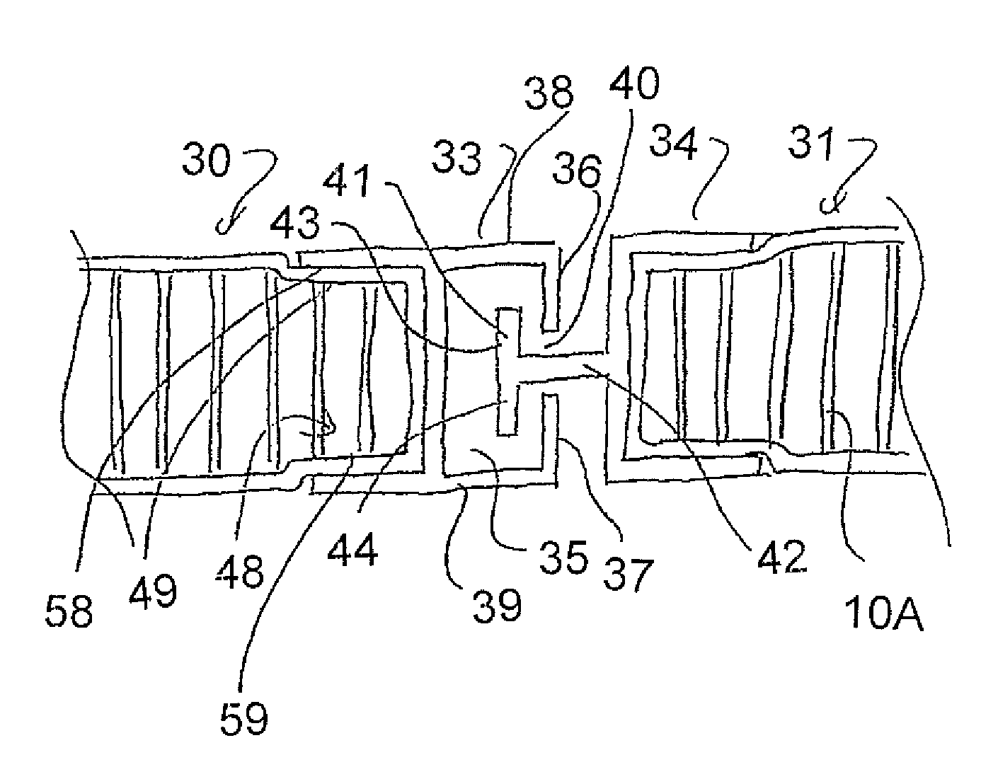
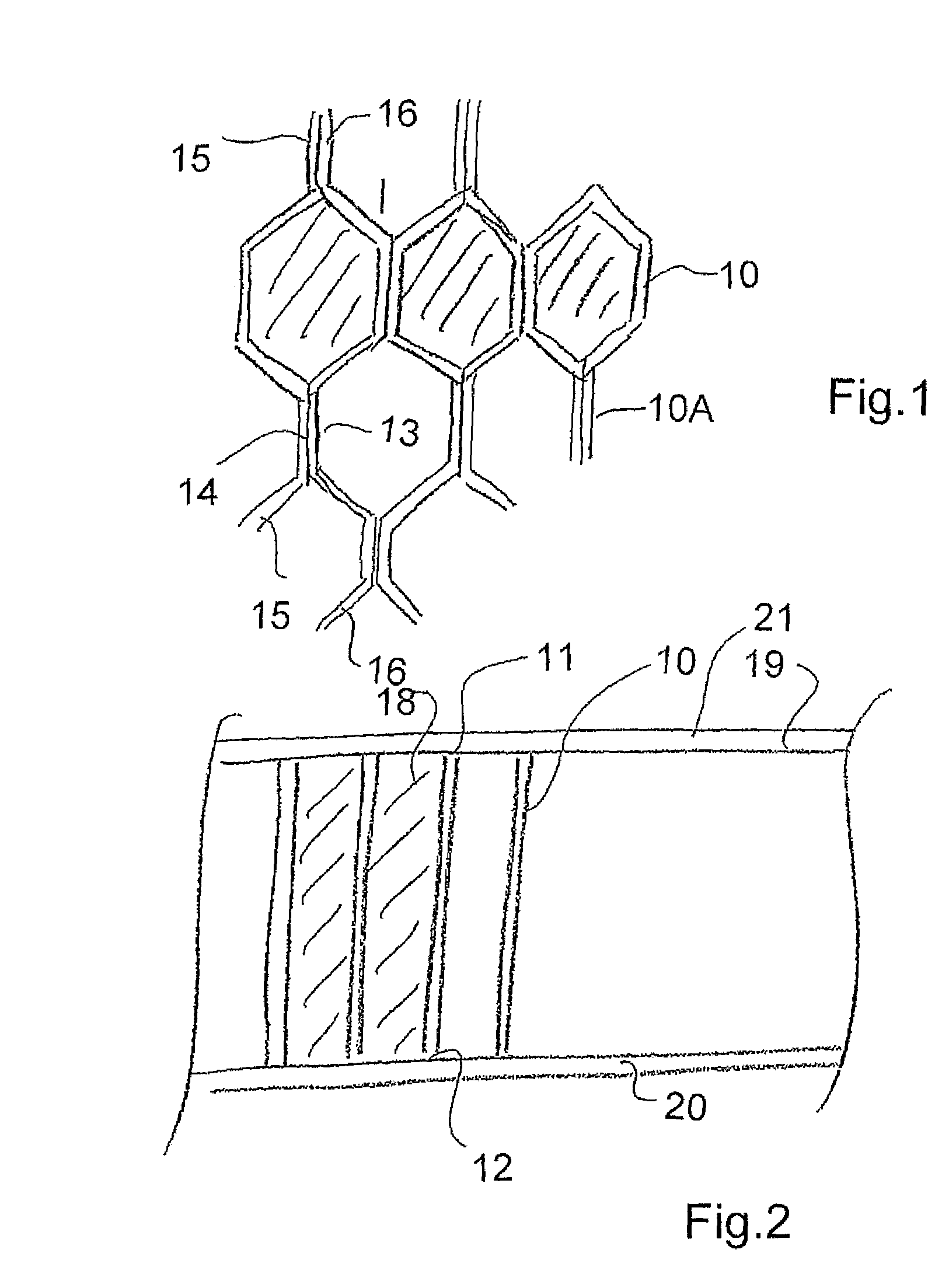
[0071]The composite panel described in general above is shown in FIGS. 1 and 2 and is formed by a honeycomb core panel 10 having a first face 11 and a second opposite face 12 with an array of generally hexagonal tubular cells defined by walls 10A of the core panel extending between the first and second faces. The cells are formed from strips 15, 16 arranged side by side of a porous fibrous material which is heat sealed at a sealing line 14 to define the generally hexagonal cells.

[0072]A foam material such as a polyurethane foam 18 fills the tubular cells.

[0073]A first fibrous reinforcing cover sheet such as a fiberglass mat (or carbon fiber, aramid fiber, Kevlar fiber, polyester fiber, natural fiber—e.g. hemp, flax, straw) 19 extends over the first face 11 of the core panel and a second fibrous reinforcing cover sheet 20 extends over the second face of the core panel.

[0074]The first and second cover sheets are filled with a set resin material 21 which extends from the cover sheets 1...


PUM

PropertyMeasurementUnit
anglesaaaaaaaaaa
heightaaaaaaaaaa
lengthaaaaaaaaaa

Abstract

A rig mat is formed by rectangular panels fastened end to end by cooperating connectors. In one arrangement the first connector is C-shaped shaped to form a slot and the second T-shaped shaped with a flange of the T wider than the mouth inserted through the mouth. In a second arrangement two L shaped connectors are interengaged with an additional flat plate which defines a slot with an end of one of the L-shaped connectors. The panels are composite and formed from a honeycomb core panel with a foam material filling the tubular cells and a fibrous reinforcing cover sheets extending over the top and bottom of the panel. The cover sheets are filled with a set resin material which extends into the porous fibrous material of the walls of the core panel so as to form an integral structure of the resin extending between the walls and the sheets.

Description

[0001]This application claims the benefit under 35 U.S.C. 119 of Provisional Application Ser. No. 61 / 059,447 filed Jun. 6, 2008.[0002]This invention relates to a rig mat system where a plurality of rectangular panels are laid side by side and fastened end to end in an array to cover rough ground to form a support surface which can be suitable for pedestrian traffic or for heavy equipment, depending on the strength of the materials selected.[0003]This application relates to the panel disclosed and claimed in application Ser. No. 12 / 355,827 filed Jan. 19, 2009 which corresponds to Canadian application 2,639,673 filed Oct. 22, 2008. The panel used herein can be of the type disclosed in the above application or other composite panels can be used.[0004]This invention can use the composite material described in the above application which is formed from a panel of a foam filled honeycomb cell material covered on top and bottom surfaces by a resin filled sheet. However the panel can also b...

Claims


Application Information

Patent Timeline
Patent Type & Authority Patents(United States)
IPC IPC(8): E04C2/38E04F15/00
CPCE01C9/086E04C2/365E04F15/10E04F2201/0107
Inventor DAGESSE, PAUL J.
Owner RHINOKORE COMPOSITES SOLUTIONS LP
Why Eureka
Try Eureka