Power connector having a signal detecting terminal on a separation member

a technology of power connector and separation member, which is applied in the direction of three-pole connection, coupling device connection, electric discharge lamp, etc., can solve the problems of easy damage to components, system load damage, and the failure of conventional power connector to comply with electric safety standards, etc., to achieve the effect of cost saving and simplified

Active Publication Date: 2011-11-22
DELTA ELECTRONICS INC
View PDF7 Cites 3 Cited by
  • Summary
  • Abstract
  • Description
  • Claims
  • Application Information

AI Technical Summary

Benefits of technology

[0007]It is an object of the present invention to provide a power connector and a power connector assembly for use in a high-voltage DC power distribution and supply system, in which the power connector and the power connector assembly are produced in a simplified and cost-effective manner.
[0008]Another object of the present invention provides a power connector assembly, in which two power connectors are securely coupled with each other without damaging the conductive terminals.
[0009]A further object of the present invention provides a power connector and a power connector assembly with detecting functions in order to avoid electric arc generation, increase electric safety and facilitate power distribution and management.

Problems solved by technology

In the high-voltage DC power distribution and supply system, the conventional power connector usually fails to comply with the electric safety standard.
Once the conventional power connector is used in the high-voltage DC power distribution and supply system, some components are readily damaged.
The generation of the electric arc may result in damage of the system load.

Method used


Image

  • Power connector having a signal detecting terminal on a separation member
  • Power connector having a signal detecting terminal on a separation member
  • Power connector having a signal detecting terminal on a separation member

Examples


first embodiment

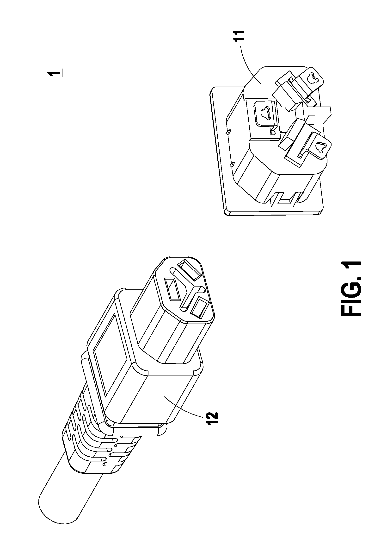
[0033]FIG. 1 is a schematic perspective view illustrating a power connector assembly according to the present invention. As shown in FIG. 1, the power connector assembly 1 comprises a first power connector 11 and a second power connector 12. In this embodiment, the first power connector 11 is a power socket, which is for example installed on a power supply. The second power connector 12 is a power plug, which is for example installed on a tip portion of a power cord. The first power connector 11 and the second power connector 12 have complementary structures. Due to the complementary structures, the first power connector 11 and the second power connector 12 are electrically with each other to produce the power connector assembly 1.

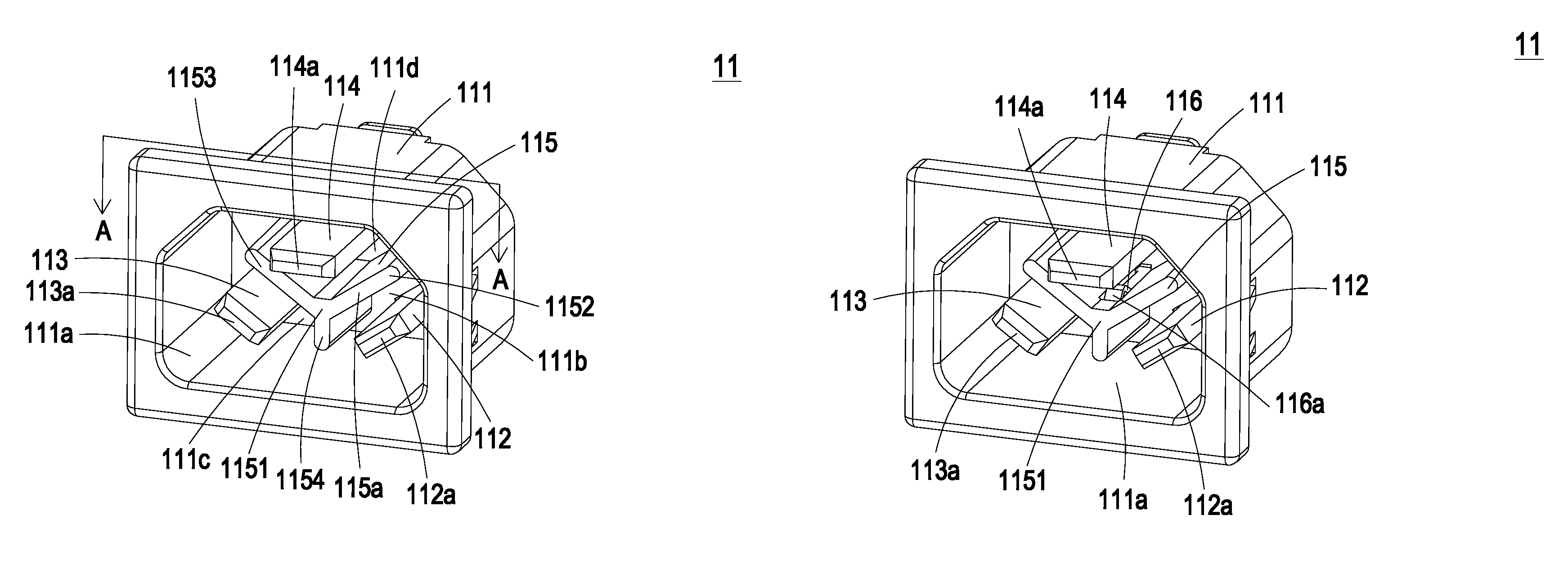
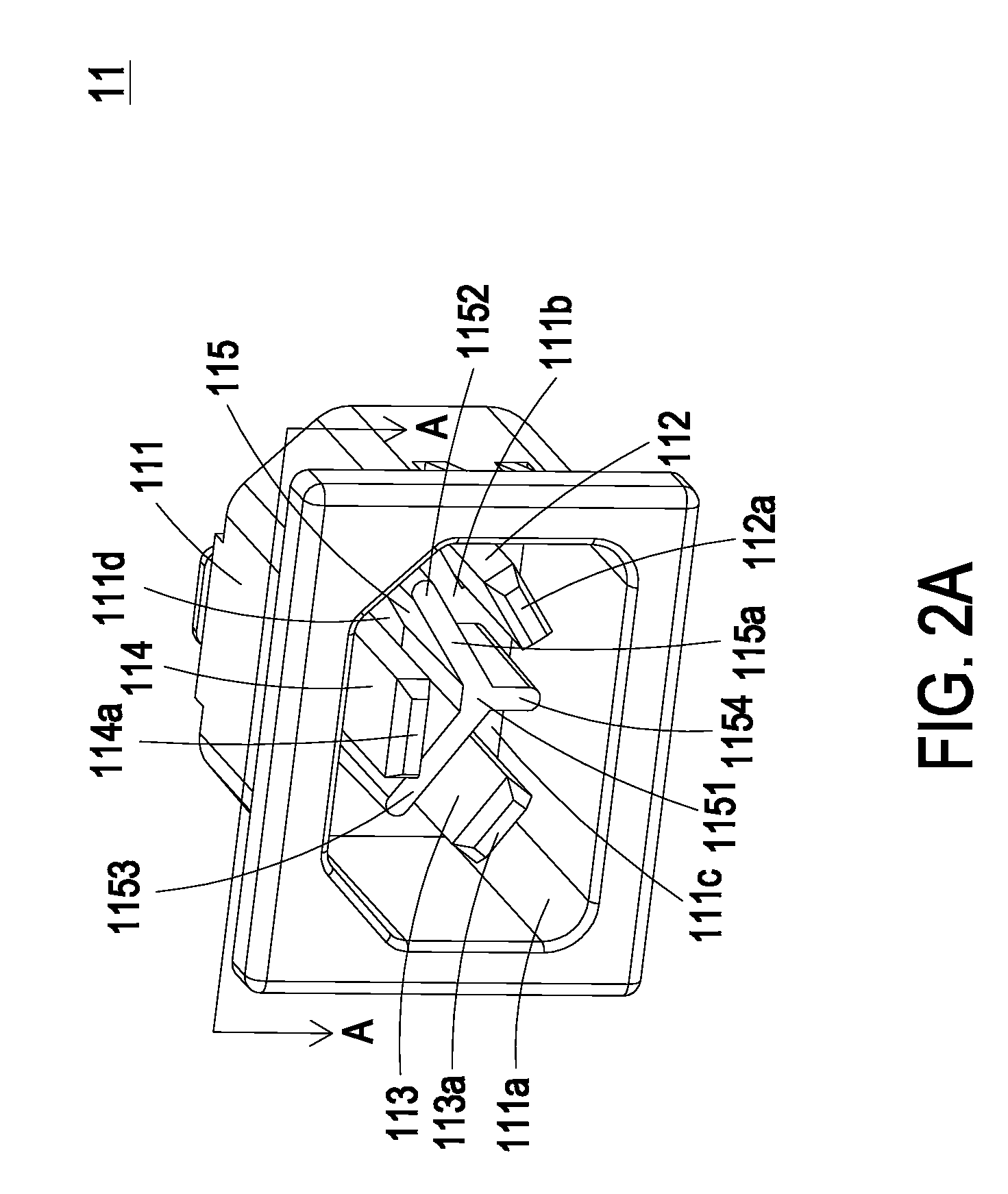
[0034]FIG. 2A is a schematic perspective view illustrating the first power connector as shown in FIG. 1. FIG. 2B is a schematic rear view illustrating the first power connector as shown in FIG. 1. FIG. 2C is a schematic cross-sectional view illustrating th...

second embodiment

[0048]FIG. 6 is a schematic perspective view illustrating a power connector assembly according to the present invention. FIG. 7 is a schematic perspective view illustrating the first power connector as shown in FIG. 6. FIG. 8 is a schematic perspective view illustrating the second power connector as shown in FIG. 6. Please refer to FIGS. 6, 7 and 8. The power connector assembly 2 comprises a first power connector 21 and a second power connector 22. In this embodiment, the first power connector 21 is a power plug, which is for example installed on a tip portion of a power cord. The second power connector 22 is a power socket, which is for example installed on a power distribution unit (PDU). The first power connector 21 and the second power connector 22 have complementary structures. Due to the complementary structures, the first power connector 21 and the second power connector 22 are electrically with each other to produce the power connector assembly 2.

[0049]The configurations and...

third embodiment

[0050]FIG. 9 is a schematic perspective view illustrating a power connector assembly according to the present invention. FIG. 10 is a schematic perspective view illustrating the first power connector as shown in FIG. 9. FIG. 11 is a schematic perspective view illustrating the second power connector as shown in FIG. 9. Please refer to FIGS. 9, 10 and 11. The power connector assembly 3 comprises a first power connector 31 and a second power connector 32. In this embodiment, the first power connector 31 is a power socket, which is for example installed on a power supply. The second power connector 32 is a power plug, which is for example installed on a tip portion of a power cord. The first power connector 31 and the second power connector 32 have complementary structures. Due to the complementary structures, the first power connector 31 and the second power connector 32 are electrically with each other to produce the power connector assembly 3.

[0051]The configurations and operating pr...


PUM


Abstract

A power connector includes a main body, a first conductive terminal, a second conductive terminal, a third conductive terminal, and an insulating separation member. The first conductive terminal, the second conductive terminal and the third conductive terminal are disposed within the main body and arranged in a non-parallel manner. The insulating separation member is disposed within the main body, and arranged between the first conductive terminal, the second conductive terminal and the third conductive terminal for separating at least two of the first conductive terminal, the second conductive terminal and the third conductive terminal from each other.

Description

CROSS-REFERENCE TO RELATED APPLICATIONS[0001]This application is a continuation-in-part of U.S. Utility patent application Ser. No. 12 / 713,764, which is entitled “POWER SUPPLY WITH ARC FLASH PROTECTION MECHANISM AND DATA-PROCESSING SYSTEM EMPLOYING SAME” and filed on Feb. 26, 2010, which claims the benefit of prior U.S. provisional application 61 / 263,895, which is entitled “INTELLIGENT POWER CONNECTOR ASSEMBLY CAPABLE OF PREVENTING GENERATION OF ARC FLASH” and filed on Nov. 24, 2009, and claims the benefit of prior U.S. provisional application 61 / 266,627, which is entitled “ARC FLASH PROTECTION MECHANISM FOR POWER SUPPLY AND DATA-PROCESSING SYSTEM EMPLOYING SAME” and filed on Dec. 4, 2009.[0002]This application also claims the benefit of prior U.S. provisional application 61 / 263,895, which is entitled “INTELLIGENT POWER CONNECTOR ASSEMBLY CAPABLE OF PREVENTING GENERATION OF ARC FLASH” and filed on Nov. 24, 2009, and claims the benefit of prior U.S. provisional application 61 / 266,627...

Claims


Application Information

Patent Timeline
Patent Type & Authority Patents(United States)
IPC IPC(8): H01R13/502
CPCH01R13/53H01R13/642H01R13/6456H01R2105/00
Inventor HUANG, YU-HUNG
Owner DELTA ELECTRONICS INC
Why Eureka
Try Eureka