Ratcheting expandable corpectomy/vertebrectomy cage

a technology of expandable implants and vertebrae, which is applied in the field of expanding implants and replacing parts of human structural anatomy with medical implants, can solve the problems of all or part of more than one vertebrae being damaged, one or more vertebrae may be damaged, and one or more vertebrae may become damaged, so as to increase the frictional resistance, and increase the overall implant height

Active Publication Date: 2011-11-22
WARSAW ORTHOPEDIC INC
View PDF89 Cites 45 Cited by
  • Summary
  • Abstract
  • Description
  • Claims
  • Application Information

AI Technical Summary

Benefits of technology

In yet another exemplary aspect, an expandable medical implant for supporting bone structures is disclosed. The implant includes a first member, a second member, and a third member. The first member may have a first outer end configured to cooperatively engage a first bone structure and a first inner end configured to engage the second member. The second member may have a second outer end configured to cooperatively engage a second bone structure and a second inner end configured to engage the first member. The second member may be axially moveable along the longitudinal axis relative to the first member to increase the overall implant height. The third member may be configured to apply a radial load that increases frictional resistance between the first and second members to selectively inhibit axial movement and an increase in the overall implant height.

Problems solved by technology

For example, one or more of the vertebrae may become damaged as a result of tumor growth, or may become damaged by a traumatic or other event.
All or part of more than one vertebrae may be damaged and require removal and replacement in some circumstances.

Method used


Image

  • Ratcheting expandable corpectomy/vertebrectomy cage
  • Ratcheting expandable corpectomy/vertebrectomy cage
  • Ratcheting expandable corpectomy/vertebrectomy cage

Examples


Embodiment Construction

For the purposes of promoting an understanding of the principles of the invention, reference will now be made to the embodiments, or examples, illustrated in the drawings and specific language will be used to describe the same. It will nevertheless be understood that no limitation of the scope of the invention is thereby intended. Any alterations and further modifications in the described embodiments, and any further applications of the principles of the invention as described herein are contemplated as would normally occur to one skilled in the art to which the invention relates.

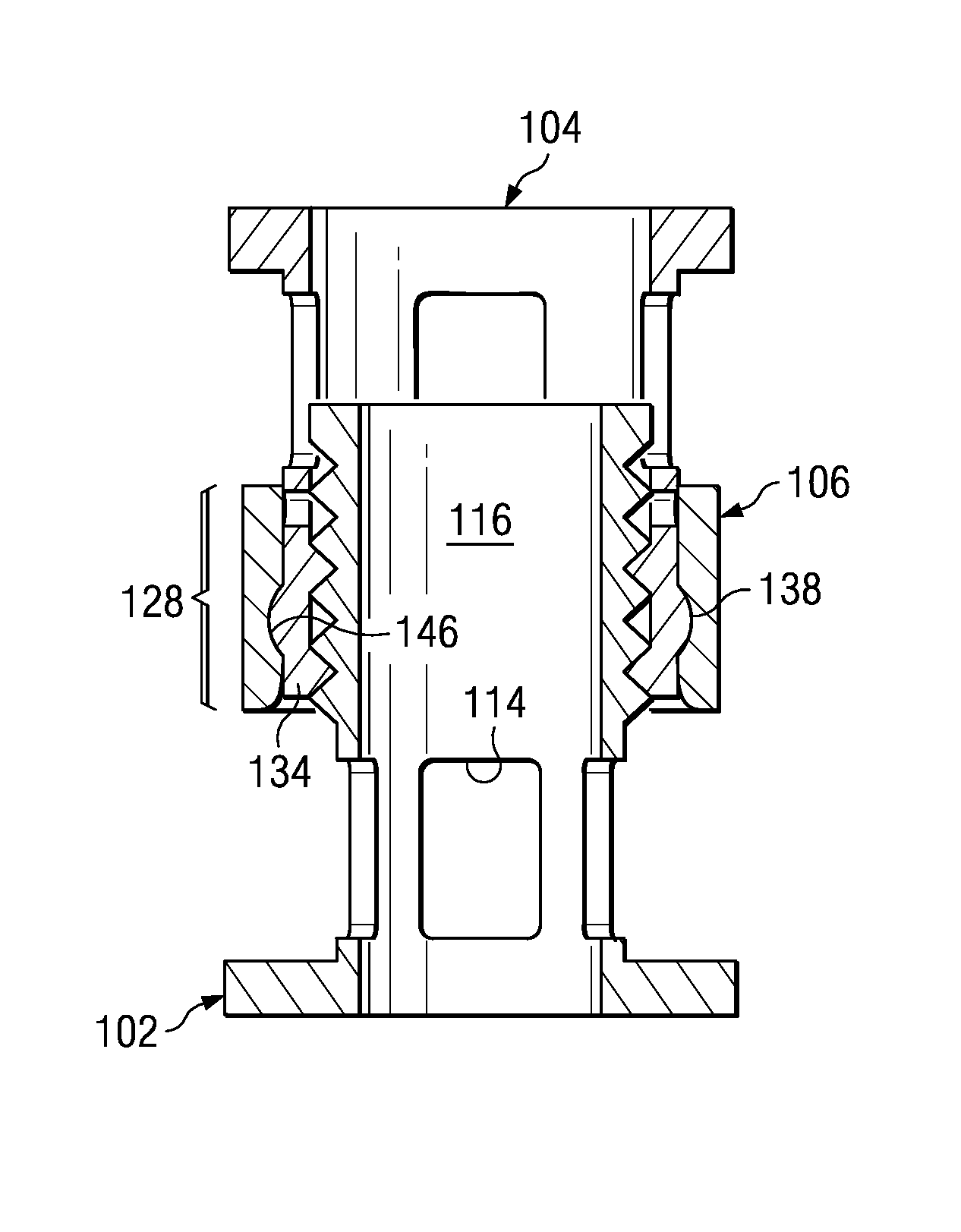
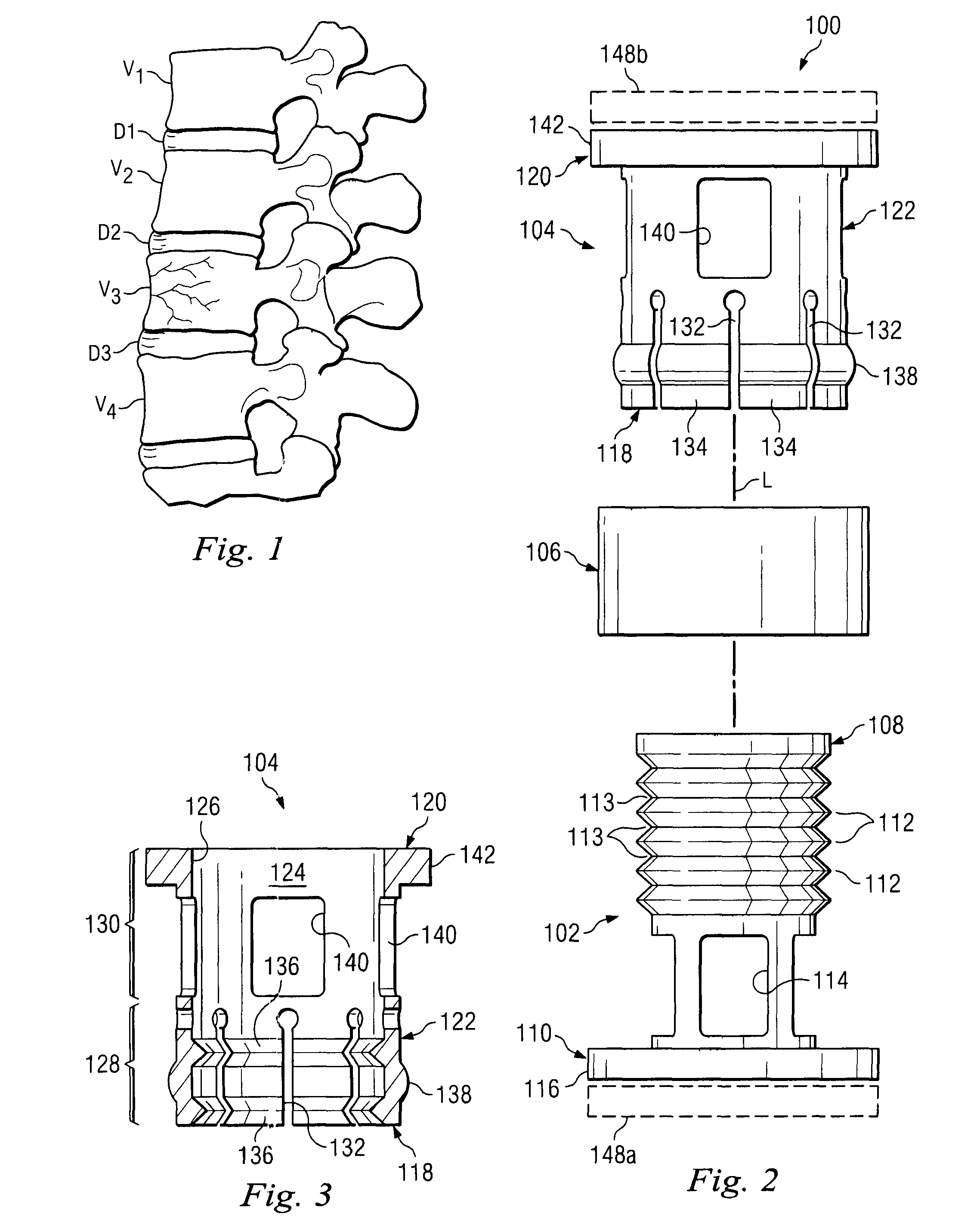
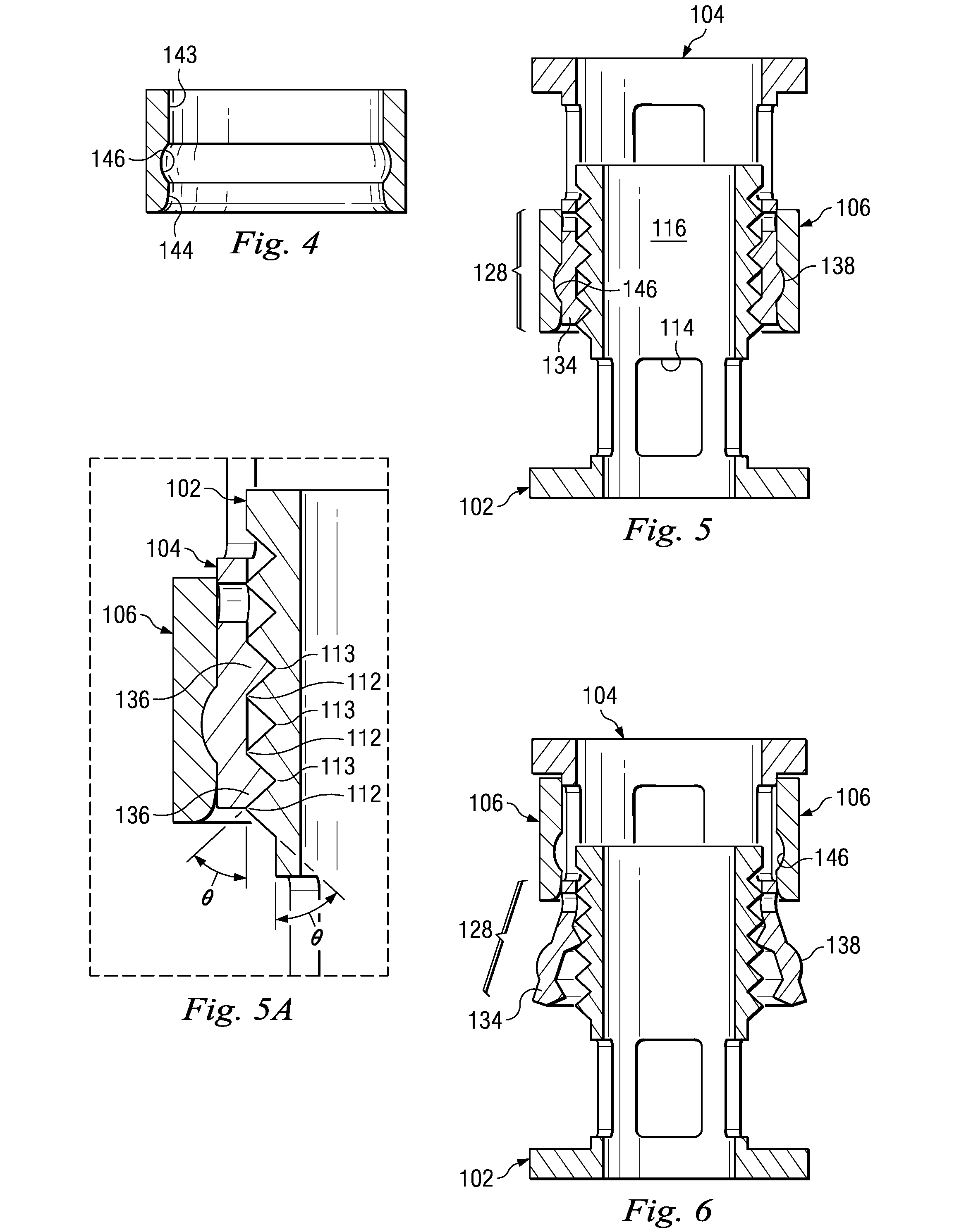
Referring now to FIG. 2, there is shown an expandable implant 100 in accordance with one aspect of the present invention. The expandable implant 100 may include an inner member 102, an outer member 104, and a locking member 106, extending along a longitudinal axis L. The inner member 102 may be formed as a tube and may include an inner end 108 configured to cooperate with the outer member 104, and an outer ...


PUM


Abstract

Expandable medical implants for supporting bone structures may include a first member and a second member. The second member may be configured to receive the first member and may be moveable along the longitudinal axis relative to the first member. One of the first and second members may include a plurality of teeth and the other of the first and second members may include at least one tooth. At least a portion of one of the first and second main bodies may be elastically deformable to selectively engage and disengage the at least one tooth and the plurality of teeth. At least one tooth and the plurality of teeth may be shaped to deform the elastically deformable portion when both increasing and when decreasing the overall implant height by moving the second member relative to the first member along the longitudinal axis.

Description

FIELD OF THE INVENTIONThe present invention relates generally to the field of replacing portions of the human structural anatomy with medical implants, and more particularly relates to an expandable implant and method for replacing bone structures such as one or more vertebrae or long bones.BACKGROUNDIt is sometimes necessary to remove one or more vertebrae, or a portion of the vertebrae, from the human spine in response to various pathologies. For example, one or more of the vertebrae may become damaged as a result of tumor growth, or may become damaged by a traumatic or other event. Excision of at least a generally anterior portion, or vertebral body, of the vertebra may be referred to as a corpectomy. An implant is usually placed between the remaining vertebrae to provide structural support for the spine as a part of a corpectomy. FIG. 1 illustrates four vertebrae, V1-V4 of a typical lumbar spine and three spinal discs, D1-D3. As illustrated, V3 is a damaged vertebra and all or a...

Claims


Application Information

Patent Timeline
Patent Type & Authority Patents(United States)
IPC IPC(8): A61F2/44
CPCA61F2/44A61F2250/0098A61F2310/00017A61F2310/00023A61F2310/00029A61F2310/00179A61F2/30965A61F2/4684A61F2002/2835A61F2002/3008A61F2002/30469A61F2002/30485A61F2002/30487A61F2002/30495A61F2002/30522A61F2002/30525A61F2002/30551A61F2002/30596A61F2002/30601A61F2002/30677A61F2002/30772A61F2002/4475A61F2220/0025A61F2002/3055A61F2002/30594A61F2002/30593
Inventor MELKENT, ANTHONY J.
Owner WARSAW ORTHOPEDIC INC
Why Eureka
Try Eureka