Post molding application of an extruded film to an injection molded part

a technology of extrusion film and injection molded parts, which is applied in the field of decorative molding parts, can solve the problems of high cost of adhesive, and high cost of decorative lamination film, and achieve the effect of cost-effectiveness

Inactive Publication Date: 2011-11-22
DELTA ENGINEERED PLASTICS
View PDF16 Cites 14 Cited by
  • Summary
  • Abstract
  • Description
  • Claims
  • Application Information

AI Technical Summary

Benefits of technology

[0011]The above methods are directed to providing a more cost-effective process for decorating molded parts. The molding process utilizes a less expensive extruded decorative film that can be applied to a molded part. The film envelops and conceals undesirable surface imperfections and distortions. Unexpectedly, the above advantages may be obtained while at the same time eliminating the need for an adhesive to bond the film to the molded part.

Problems solved by technology

One of the problems that faces implementation of film decoration of products includes the cost of the process of applying an adhesive to the film and the cost of the adhesive.
The cost of decorative lamination films may add substantial cost to the finished product.
In addition, surface imperfections and contaminants, such as dust, may be visible or even magnified by the film when the decorated part is observed or inspected.

Method used


Image

  • Post molding application of an extruded film to an injection molded part
  • Post molding application of an extruded film to an injection molded part
  • Post molding application of an extruded film to an injection molded part

Examples


Embodiment Construction

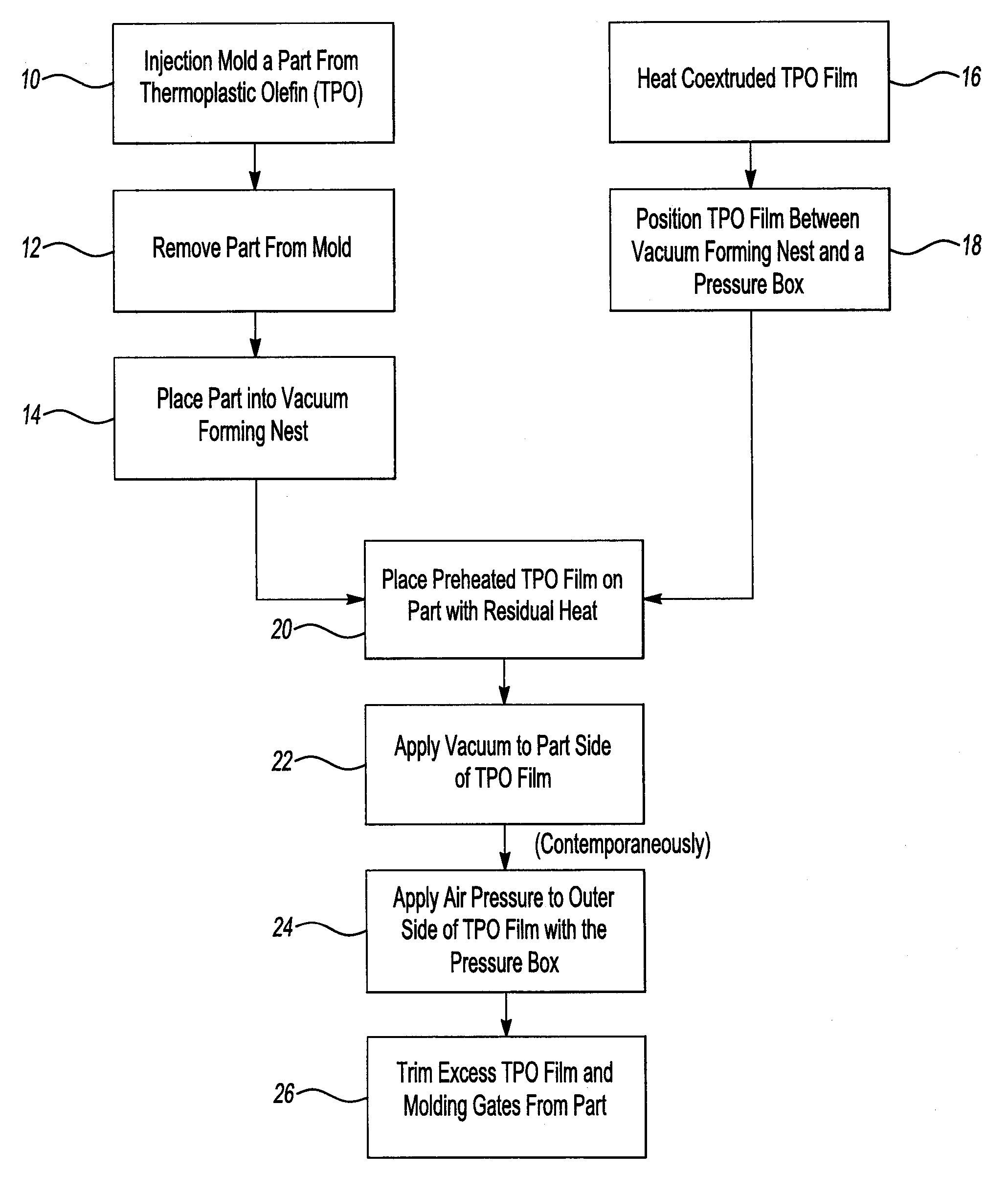
[0016]The following description makes reference to the attached flowchart of the process as depicted in FIG. 1. The process is described beginning with injection molding a part from an amorphous or semi-crystalline thermoplastic resin. Examples of such resins include acrylonitrile butadiene styrene (ABS), polycarbonate / ABS, and thermoplastic olefin resin (hereinafter “TPO”). TPO is the resin referred to herein as an example throughout this application, but the invention should not be construed as being limited to TPO. Specific references to TPO should generally be understood to include amorphous or semi-crystalline thermoplastic notwithstanding differences in melting temperatures and other characteristics.

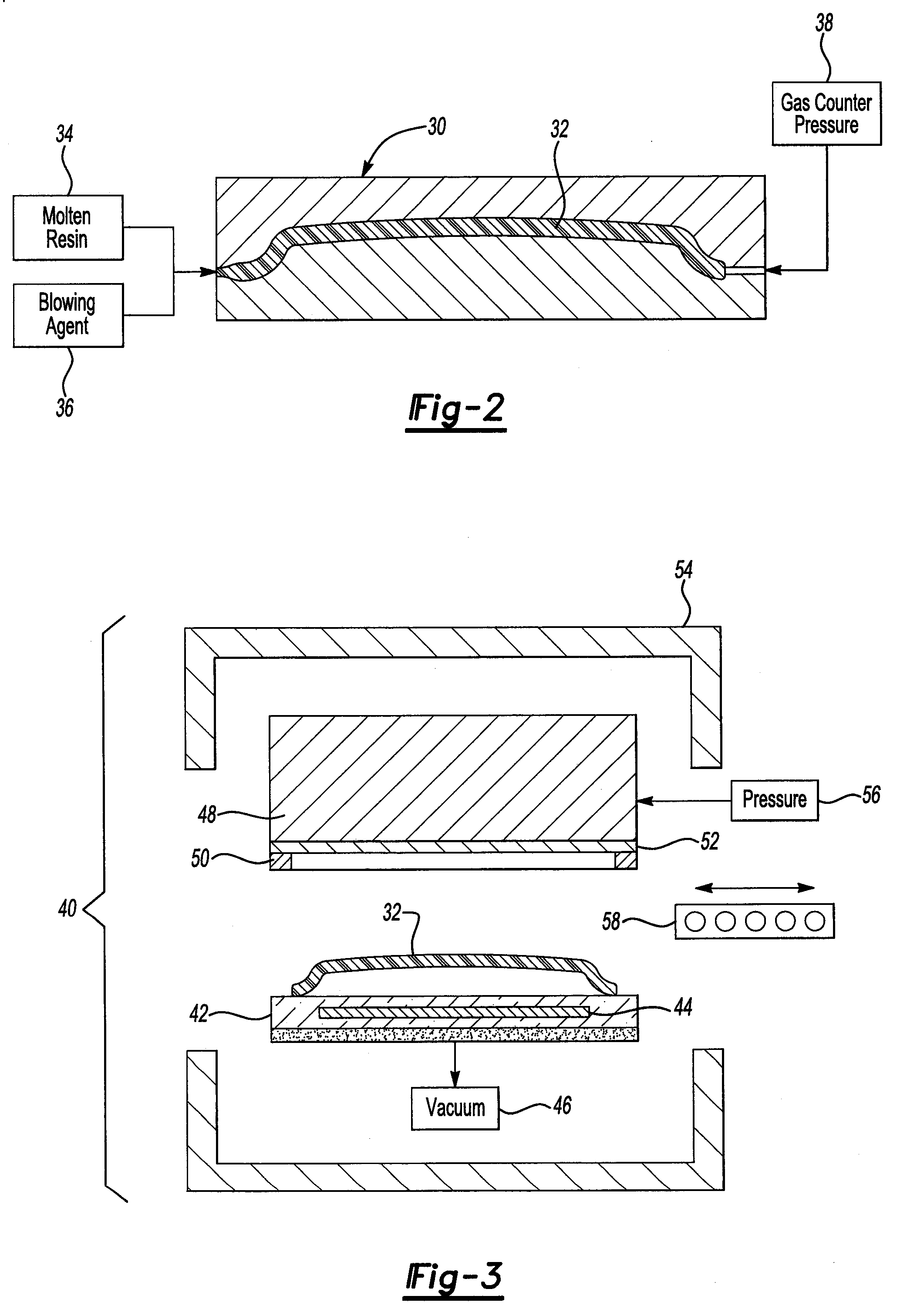
[0017]The part is preferably injection molded, at 10, from either solid TPO or from mechanically or chemically foamed TPO, that is injection molded with or without gas counter pressure. The TPO is injected into the mold at its melt temperature, which is about 220° C. The molded par...


PUM

PropertyMeasurementUnit
temperatureaaaaaaaaaa

Abstract

A method of laminating a decorative layer to a molded part comprises molding a part formed of an amorphous or semi-crystalline thermoplastic resin and applying a segment of co-extruded an amorphous or semi-crystalline thermoplastic resin film to the part. The part is loaded into a vacuum forming nest and maintained in a heated state. The film is heated and then positioned over the part in a pressure box. A vacuum is applied through the vacuum forming nest to a first side of the film facing the part at the same time air pressure is applied through the pressure box to a second side of the film. The film is bonded directly to the part without the need for an adhesive.

Description

CROSS-REFERENCE TO RELATED APPLICATIONS[0001]This application claims the benefit of U.S. provisional application Ser. No. 61 / 030,701 filed Feb. 22, 2008.BACKGROUND OF THE INVENTION[0002]1. Field of the Invention[0003]The present invention relates to the field of decorating molded parts by applying a decorative film to the part.[0004]2. Background Art[0005]Molded parts may be provided as bare undecorated parts or may be decorated by painting. Recently, molded parts such as bumpers, grill surrounds, light bezels, sun visors and other vehicle components have been developed that are decorated with a film product that includes a fluoropolymer clear coat, an indium bright layer, a tie coat and primer and a heat-activated adhesive layer. The indium bright layer may have a chrome-like appearance that is UV resistant, weather resistant and resistant to corrosive materials and stone chips.[0006]One of the problems that faces implementation of film decoration of products includes the cost of t...

Claims


Application Information

Patent Timeline
Patent Type & Authority Patents(United States)
IPC IPC(8): B29C65/00B32B37/00
CPCB29C66/45B29C66/82661B32B27/08B29C51/16B29C65/02B29C66/301B29C66/305B29C65/1432B29C66/73921B29C66/73772B29C66/73774B32B5/18B32B27/06B32B27/065B32B27/302B32B27/304B32B27/308B32B27/32B32B27/322B32B27/36B32B27/365B29C66/8266B32B2605/00B29C66/919B29C2035/0822B29C2791/001B29C2791/006B29C2791/007B29K2023/00B29K2101/12B29K2995/0039B29K2995/004B29L2031/3044B29C45/00B29C51/14B29C65/1412B29C66/91413B29C66/91445Y10T156/1074B32B2255/10B32B2255/205B32B2266/0214B32B2266/025B32B2270/00B32B2307/4026B32B2307/702B32B2451/00B29C66/1122B29C66/5326B29C66/727B29C44/5681B29C63/0073B29C63/02B29C65/028B29C69/007B29C66/71B29C66/723
Inventor MOZER, WILFRIEDDESMITH, BRIAN L.
Owner DELTA ENGINEERED PLASTICS
Why Eureka
Try Eureka