Tilting-type automatic pouring method and a medium that stores programs to control the tilting of a ladle

a technology of automatic pouring and tilting, which is applied in the field of casting technology, can solve the problem that none of them controls the position where the molten metal drops

Active Publication Date: 2011-11-22
SINTOKOGIO LTD +1
View PDF11 Cites 8 Cited by
  • Summary
  • Abstract
  • Description
  • Claims
  • Application Information

AI Technical Summary

Benefits of technology

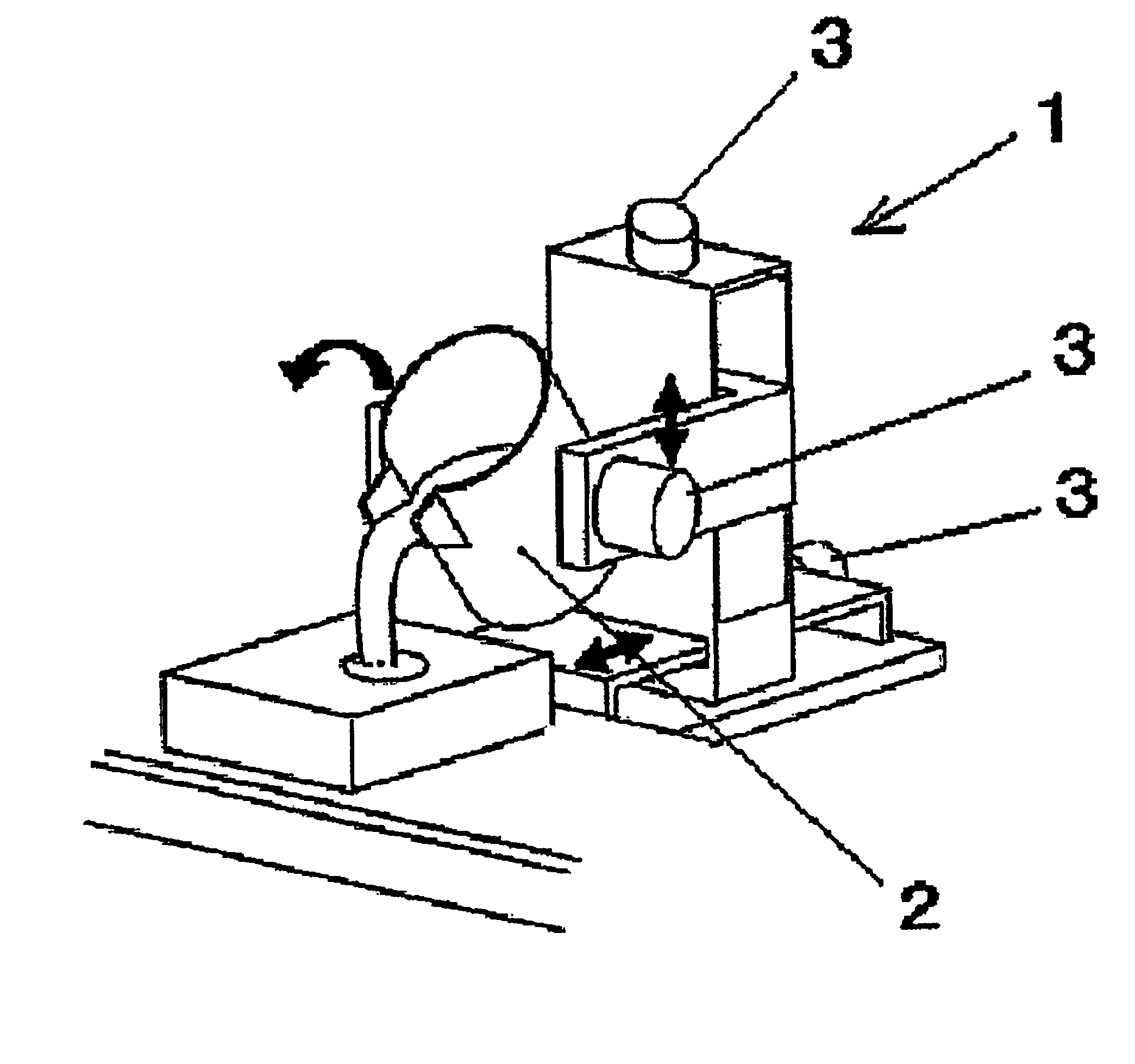
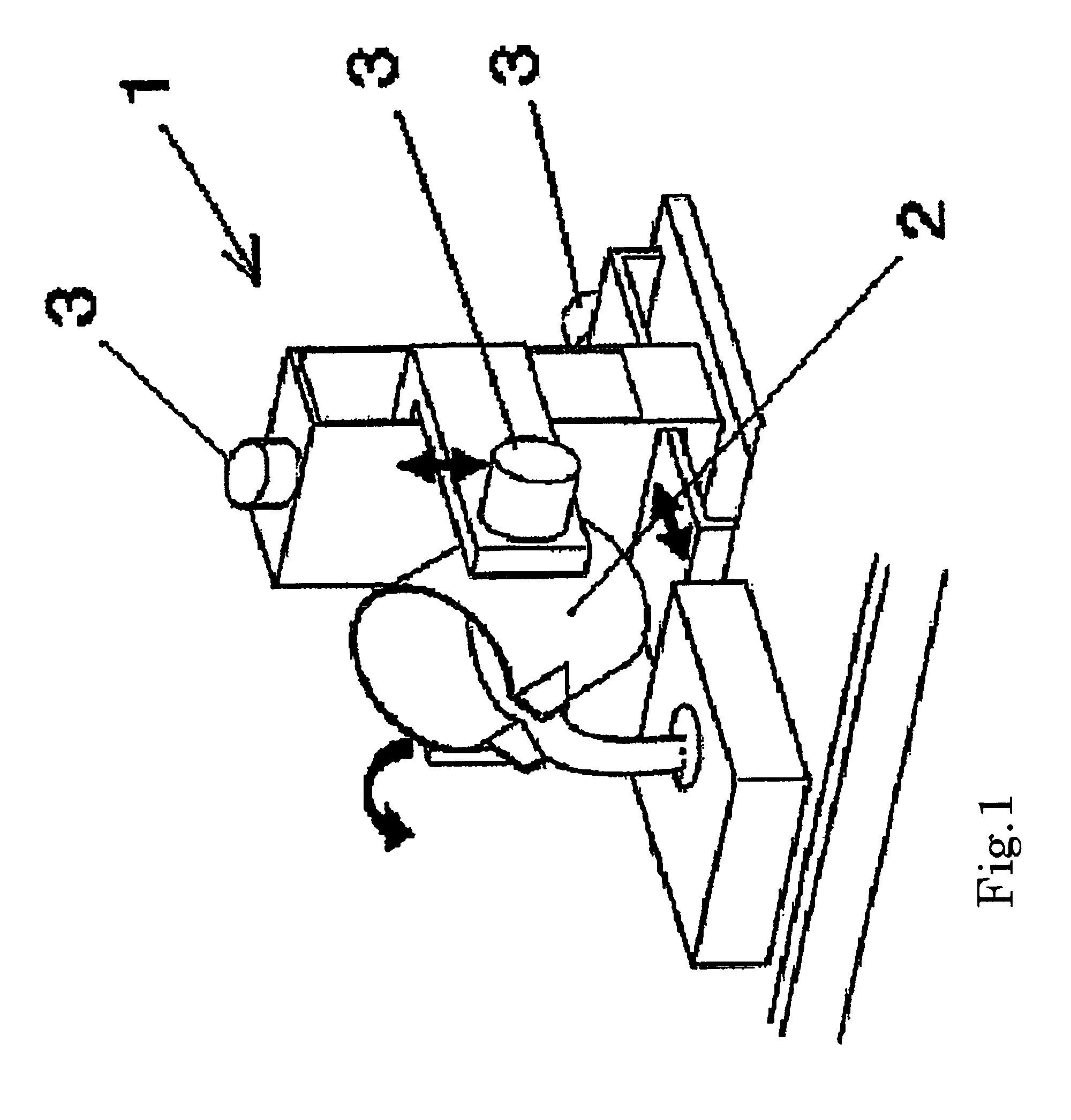
[0020]To achieve the above objective, the tilting-type automatic pouring method of the present invention is one for a tilting-type automatic pouring apparatus provided with a servomotor that controls the tilting of a ladle that holds molten metal, one that controls the backward and forward movement of the ladle, and one that controls the lifting and lowering of the ladle, whereby the molten metal is poured into a mold by the tilting of the ladle,
[0029]The present invention provides a method to precisely drop the molten metal that flows from the ladle into the sprue of the mold by moving the ladle backward and forward and controlling the position where the molten metal drops. In this way the molten metal does not miss the position of the drop in the pouring process and it drops precisely in the sprue, whereby the pouring can be done safely and without any loss of the molten metal.BEST MODE OF CARRYING OUT THE INVENTION

Problems solved by technology

None of them controls the position where the molten metal drops when the tilting-type automatic pouring method is used.
Thus there still remains a problem in that the position of the molten metal poured from the ladle often drops outside a sprue, and that problem should be addressed.Patent Document 1: Publication of a Japanese Patent Application, Publication No.

Method used


Image

  • Tilting-type automatic pouring method and a medium that stores programs to control the tilting of a ladle
  • Tilting-type automatic pouring method and a medium that stores programs to control the tilting of a ladle
  • Tilting-type automatic pouring method and a medium that stores programs to control the tilting of a ladle

Examples


examples

[0089]FIG. 8 shows the locus of the positions where the molten metal drops as obtained from the simulated tests, which locus indicates the usefulness of the system for controlling the position where the molten metal drops. FIG. 8 is a projected top view of the pouring system. Fig. (a) shows the results when the position where the molten metal drops is controlled and Fig. (b) shows the results when the position where the molten metal drops is not controlled. The thin line shows the cup of the sprue, the bold line shows the area where in the experiments the molten metal spreads farthest from the center of the cup of the sprue (the diameter of the molten metal that spreads), the dotted line shows where the center of the molten metal that drops and the center of the cup of the sprue are the farthest possible distance apart. The results show that when the system that controls the position where the molten metal drops is used, the molten metal drops into the cup of the sprue even if it is...


PUM

PropertyMeasurementUnit
voltagesaaaaaaaaaa
speedaaaaaaaaaa
voltageaaaaaaaaaa

Abstract

A method for controlling a ladle to pour molten metal into a sprue of a mold. The method includes obtaining a mathematical model describing a locus of positions where the molten metal flowing from the ladle drops on an upper surface of the sprue. The method further includes solving an inverse problem of the mathematical model, estimating a position where the molten metal drops using a result of the solving of the inverse problem, and determining target voltages to be supplied to servomotors controlling the ladle. At least the target voltage to be supplied to one of the servomotors is determined based on the estimated position. The method also includes controlling the servomotors based on respective target voltages.

Description

TECHNICAL FIELD[0001]This invention relates in general to casting technology. In particular it relates to a tilting-type automatic pouring method wherein an amount of molten metal, such as a ferrous molten metal or aluminum molten metal, is held in a ladle, and the molten metal is poured into a mold by tilting the ladle.BACKGROUND TECHNOLOGY[0002]Various conventional tilting-type automatic pouring methods are known, such as shown below:[0003]1) the method that controls the vibrations of molten metal when it is transported to the pouring position (Patent Document 1)[0004]2) the method that controls the vibrations of molten metal caused by the backward tilting of the ladle at the completion of pouring (Patent Document 2)[0005]3) the method that controls the speed of the tilting of the ladle so as to maintain the constant flow of metal (Patent Document 3)[0006]4) the method that completes the pouring of the predetermined weight of the molten metal in a short time (Patent Document 4)[00...

Claims


Application Information

Patent Timeline
Patent Type & Authority Patents(United States)
IPC IPC(8): B22D41/06
CPCB22D37/00B22D41/06B22D46/00
Inventor NODA, YOSHIYUKITERASHIMA, KAZUHIKOMIYOSHI, TAKANORIOTA, KAZUHIROSUZUKI, MAKIO
Owner SINTOKOGIO LTD
Why Eureka
Try Eureka