
Hammock arch

a hammock and arch technology, applied in the field of hammocks, can solve the problems of limited use of the hammock, inconvenient transportation, and inability to modularize the hammock, and achieve the effects of convenient conversion, convenient assembly and disassembly, and strength and stability regardless of terrain or ground conditions

Inactive Publication Date: 2011-11-29
EWING JAY
View PDF16 Cites 11 Cited by
  • Summary
  • Abstract
  • Description
  • Claims
  • Application Information

AI Technical Summary

Benefits of technology

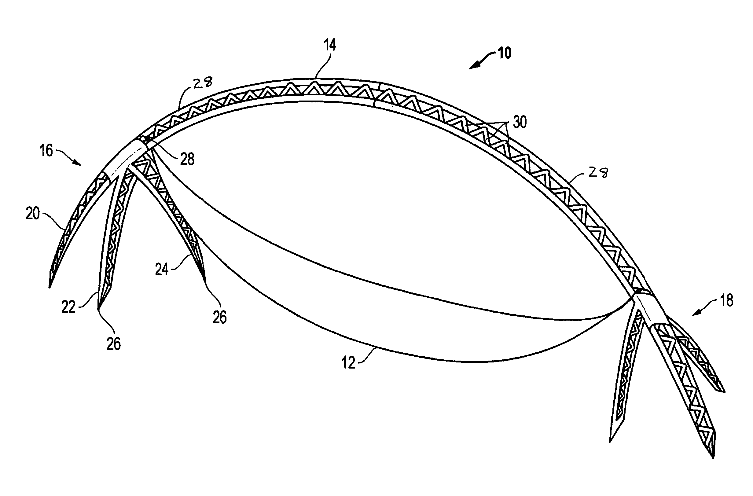
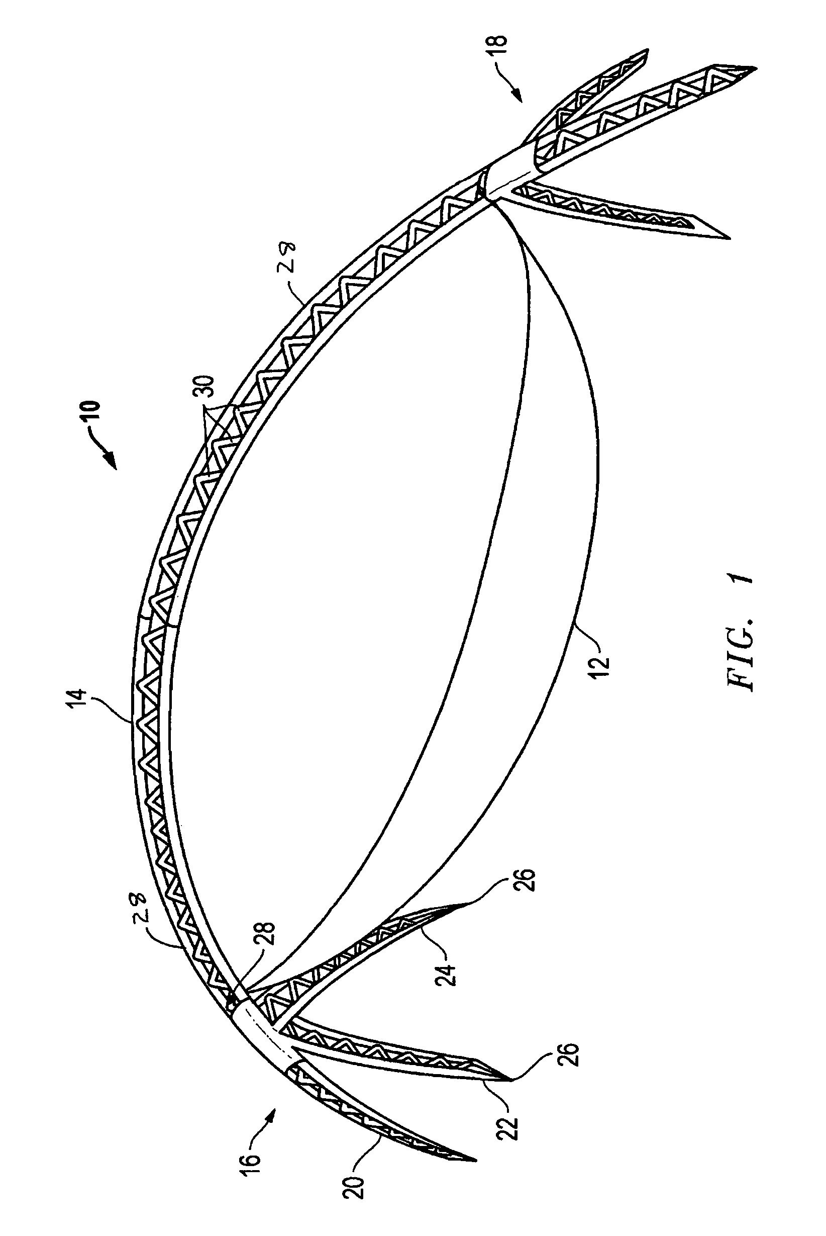
[0008]An object of the invention is to provide a portable hammock support assembly that provides ease of assembly and disassembly, provides strength and stability regardless of terrain or ground conditions, and is easily convertible for a variety of uses.
[0009]The hammock support assembly includes an arched structure supported by tripod leg supports. The arched structure preferably provides multiple attachment points to support items, such as a hammock bed for varying the types, lengths, and heights of hammocks. The tripod leg supports provide stability for use in wet, uneven, or otherwise inhospitable terrain. The stability of the tripod leg supports and the strength of the arched structure provides ease of entry and exit for weight and balance support in any location.

Problems solved by technology

This assembly has limited use in that there is only one point of connection at each end of the frame from which to suspend the hammock bed.
This assembly is not modular and is not easily transportable.
This assembly is limited because the support frame includes only a single attachment point for the hammock.
Additionally, the tubular construction provides less strength and stability than is often desired.
This assembly is limited with only one attachment point at each end for the hammock bed.
Additionally, this assembly requires a beam that extends underneath the hammock bed that could cause injury should the hammock bed fall.
This assembly is complicated in design the single tubular frame structure does not provide optimal strength and support.
This assembly requires tools for assembly and is limited in design and use.

Method used


Image

  • Hammock arch
  • Hammock arch
  • Hammock arch

Examples


Embodiment Construction

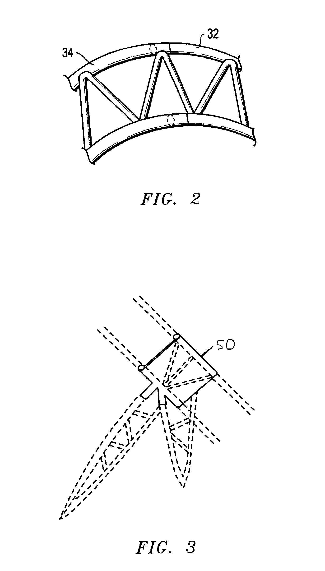
[0019]A preferred embodiment of the hammock assembly of the invention includes an arched structure supported by tripod leg supports, the arch opening downward so that the high point of the arch is toward the center. The arched structure is preferably a truss structure, that is, it is composed of at least two longitudinal members and cross-support members, between the two longitudinal members, the cross-support members preferably extending at a non-normal angle to the longitudinal members.

[0020]The truss structure provides multiple attachment points to support a hammock bed for varying the types, lengths, and heights of hammocks. The strength of the truss permits the hammock support to be made of a thinner material than a comparable support using a non-truss structure. The truss can be of uniform width between the longitudinal members, or the width can be varied. For example, the longitudinal members may be further apart at the top and approach toward a point at the tripod leg, or th...


PUM


Abstract

A hammock support is provided that includes an arched structure supported by tripod leg supports. The arched support is preferably a truss structure that provides multiple attachment points to support a hammock bed for varying the types, lengths, and heights of hammocks. In some embodiments, the arched truss structure includes multiple interlocked truss sections that can be assembled and disassembled without tools. The tripod leg supports provide stability for use in wet, uneven, or otherwise inhospitable terrain. The arched structure provides attachment locations for one or more accessories, such as mosquito netting, tents, tables, drink holders, lights, and other accessories. Additionally, the hammock support assembly of the invention is adapted to be used with one or more hammock support assemblies to create larger structures to create tents or bivouacs for camping or emergency shelter.

Description

[0001]This application claims the benefit of U.S. Provisional Pat. App. No. 60 / 522,414 filed Sep. 28, 2004, which is hereby incorporated by reference.TECHNICAL FIELD OF THE INVENTION[0002]The present invention relates generally to hammocks and more particularly to an improved hammock arch assembly that provides strength and flexibility in use.BACKGROUND OF THE INVENTION[0003]Hammock assemblies are well known and are available in a variety of configurations. One example is shown and described in U.S. Pat. No. 2,251,299, in which a hammock is suspended from a connecting thrust bar assembly. The thrust bar assembly is constructed of interlocked steel tubing connected to support legs at each end. The hammock includes cords at each end that engage with hooks located on the support leg assemblies. Alternatively, the hammock may be suspended by chains at each end that extend through perforations formed in a socket plate in the support leg assemblies. This assembly has limited use in that t...

Claims


Application Information

Patent Timeline
IPC IPC(8): A45F3/24
CPCA45F3/24
Inventor EWING, JAY
Owner EWING JAY
Learn More