
Surface treatment device

A surface treatment device and surface treatment technology, applied in transportation and packaging, lighting and heating equipment, furnace components, etc., can solve the problems of reduced productivity, prone to mechanical conflicts, uneven surface treatment conditions, etc., to prevent non-conductor , Improving the delivery accuracy and reducing the effect of holding force

Inactive Publication Date: 2004-04-21
ALMEX PE INC
View PDF0 Cites 1 Cited by
  • Summary
  • Abstract
  • Description
  • Claims
  • Application Information

AI Technical Summary

Problems solved by technology

[0011] Therefore, the interval (Dw(Ds)) between the rear end of the adjoining front plate (Ws(Wn)) and the front end of the rear plate (Dn(D1)) cannot be maintained electrically as one in appearance. Positional relationship of continuous faces, or prone to other undesirable conditions
[0012] That is, when the front-to-back distance increases (Dn→Dw), since electric power concentration occurs on the rear end of the adjacent front plate-shaped object (Ws) and the front end of the rear plate-shaped object (Wn), each plate-shaped object (surface ) surface treatment conditions are not uniform, and the surface treatment quality deteriorates
On the other hand, when the distance between front and rear is reduced (Dn→Ds), mechanical conflicts are likely to occur on the rear end of the adjacent front plate (Wn) and the front end of the rear plate (W1).
[0013] Therefore, adjusting and changing the installation position (pitch p) of the above-mentioned installation parts 90 on the conveying mechanism (for example, a chain conveyor) to a correct interval through the tightening and tightening of bolts and nuts will greatly reduce productivity.
Moreover, when the installation method is welding or when there is a suspension mechanism between each jig and the transport mechanism, not only is it more complicated and time-consuming, but also adjustment and change operations are often impossible.

Method used


Image

  • Surface treatment device
  • Surface treatment device
  • Surface treatment device

Examples


Embodiment Construction

[0044] Hereinafter, embodiments of the present invention will be described in detail with reference to the drawings.

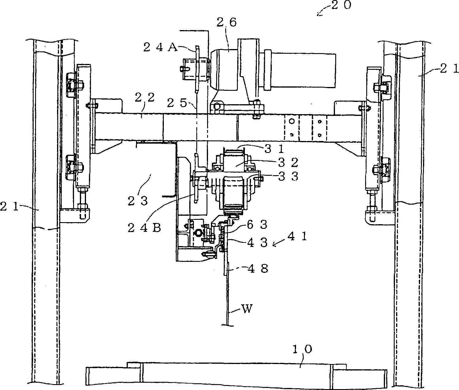
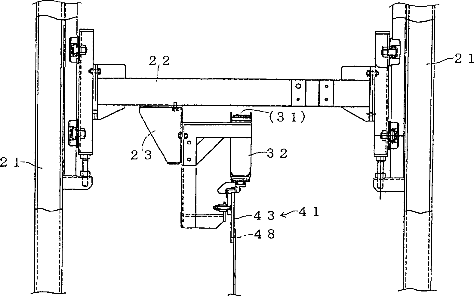
[0045] Surface treatment device of the present invention such as Figure 1 to Figure 6 As shown, the conveyer 31 that can move the conveying mechanism 20 in the conveying (X) direction can maintain a vertical hanging posture with a plurality of hangers 41 that hold a flat object (work W) at intervals in the X direction. The suspension loading and unloading mechanism 51 that is installed or separated on the conveyor 31 under the state of the suspension is constituted, and this suspension loading and unloading mechanism 51 has a plurality of ring-shaped materials 54 and A plurality of protruding materials 58 installed on one side of each suspension (or one side of the conveyor) can be engaged and separated by elastic deformation of both (or at least one of) the ring material 54 and the protruding material 58, At the same time, in the engaged state of both 54 an...


PUM


Abstract

The invention provides surface treatment equipment which is capable of improving surface treatment quality and production efficiency while facilitating the adjustment of mounting spacings in the conveying direction of flat shaped objects and facilitating the attachment and detachment of the flat shaped objects. A conveyance mechanism for conveying the flat shaped objects is formed of a conveyor, hangers and hanger attaching and detaching means. The hanger attaching and detaching means have plural loop materials attached to either one of the conveyor side and the respective hanger sides and plural projecting materials attached to the other thereof, are engageable and separable with and from each other by utilizing the elastic deformation of at least either or both of the loop materials and the projecting materials and are formed strong to the tensile force in the conveyance direction and weak to the tensile force in the direction orthogonal with the conveyance direction in the engaging state of both.

Description

technical field [0001] The present invention relates to a conveying mechanism which maintains the vertical hanging posture of the flat object and conveys the flat object in the conveying direction along the conveying route. The power supply mechanism supplies power to the flat object being conveyed in the surface treatment tank And implement the surface treatment device for surface treatment. Background technique [0002] In the surface treatment method of the object to be treated, the treatment tanks arranged in advance can be transported sequentially, the object to be treated is immersed in the first treatment tank, the treatment is performed only for a specified time, and the object to be treated is pulled up after the treatment. , transported to the next treatment tank, and only the specified time of the treatment is carried out in the next treatment tank. There are a batch method in which the same procedure is repeated, and a continuous method in which the object to be...

Claims


Application Information

Patent Timeline
IPC IPC(8): C25D17/06B65G49/02C25D7/12H05K3/00H05K13/00
CPCB65G49/061C25D17/06
Inventor 安斋文夫
Owner ALMEX PE INC
Learn More