Cyclic support structure, permanent support structure, and tunnel support method
A structural and permanent technology, which is applied in the fields of permanent support structure, tunnel support, and circular support structure, and can solve problems such as poor support effect, complex structure, and inconvenient support at the bottom of the arch foot of the steel arch.
- Summary
- Abstract
- Description
- Claims
- Application Information
AI Technical Summary
Problems solved by technology
Method used
Image
Examples
Embodiment 1
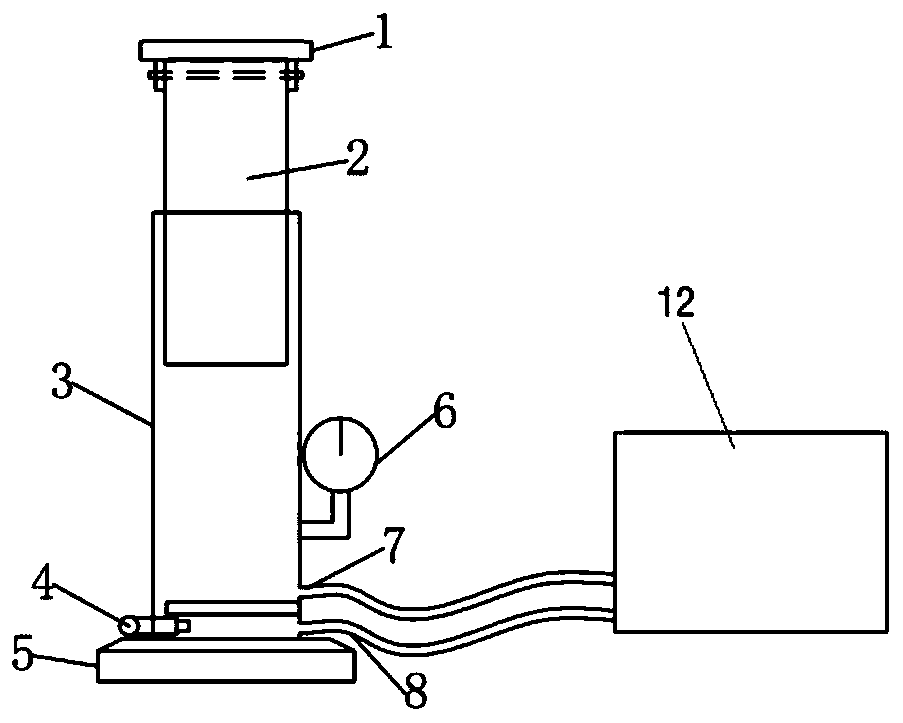
[0035] like figure 2 , Figure 5 As shown, this embodiment provides a cyclic support structure 14, including a hydraulic cylinder, the hydraulic cylinder includes a cylinder body 3 and a hydraulic column 2, the inner chamber of the cylinder body 3 communicates with the hydraulic station 12; the hydraulic column 2 The end of the support plate 1 is hinged to one side of the support plate 1, so that the support plate 1 can rotate along the end of the hydraulic column 2 within a set angle range, and the support plate 1 is used to support the arch foot.
[0036] The oil in the cylinder body 3 can flow back into the hydraulic station 12 after the arch foot in the tunnel is stabilized, so as to realize the unloading and removal of the hydraulic cylinder.
[0037] Specifically, in this embodiment, an oil inlet 7 and an oil outlet 8 are provided on the side of the cylinder body, and the oil inlet and the oil outlet are respectively communicated with the hydraulic station through oil ...
Embodiment 2
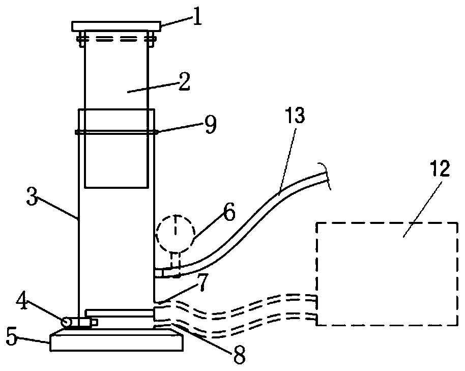
[0043] like image 3 , 4 , 5, 7, and 8, this embodiment provides a permanent support structure 15, including a hydraulic cylinder, the hydraulic cylinder includes a cylinder body 3 and a hydraulic column 2, and the inner cavity of the cylinder body 3 communicates with the hydraulic station 12 The end of the hydraulic column 2 is hinged to one side of the support plate 1, so that the support plate 1 can rotate along the end of the hydraulic column 2 within a set angle range, and the support plate 1 is used to support the arch foot;
[0044] The side of the cylinder 3 is provided with a grouting hole, and the grouting hole can be communicated with the grouting equipment through the pipeline, and the grouting equipment can flow to the cylinder 3 after the oil in the cylinder 3 flows back into the hydraulic station 12. 3 Cement slurry is injected into the inner cavity to realize the permanent fixation of the cylinder body 3 and the hydraulic column 2.
[0045] In this embodiment, ...
Embodiment 3
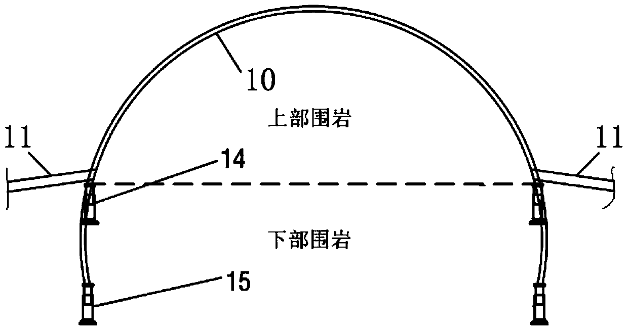
[0053] like figure 1 , 6 As shown, the present embodiment provides a tunnel support method for step method construction, comprising the following steps:
[0054] Excavate the upper steps to the set depth, erect the upper arch, and support the arch feet of the upper arch through the circular support structure 14; inject hydraulic oil into the cylinder 3 of the circular support structure 14, and the upper arch will follow the hydraulic column 2 Rise to a set distance and complete the temporary support of the upper surrounding rock;
[0055] The surrounding rock above the upper steps is deformed and stabilized, and the bolts are used to support the arch foot at the upper arch, and the circular support structure 14 is removed. The anchor rod here can adopt the foot anchor rod 11.
[0056] Excavate the lower steps to the set depth, erect the lower support frame, the arch foot of the upper arch frame is fixedly connected with the upper end of the lower support frame, and the arch...
PUM
 Abstract
Description
Claims
Application Information
 - R&D
- Intellectual Property
- Life Sciences
- Materials
- Tech Scout
- Unparalleled Data Quality
- Higher Quality Content
- 60% Fewer Hallucinations
Browse by: Latest US Patents, China's latest patents, Technical Efficacy Thesaurus, Application Domain, Technology Topic, Popular Technical Reports.
© 2025 PatSnap. All rights reserved.Legal|Privacy policy|Modern Slavery Act Transparency Statement|Sitemap|About US| Contact US: help@patsnap.com


