Recording device

a recording device and recording technology, applied in the direction of thin material processing, article separation, printing, etc., can solve the problems of manual sliding, difficult sliding of the shutter, and a risk, and achieve the effect of stabilizing the relative positional relationship

Active Publication Date: 2011-11-29
SEIKO EPSON CORP
View PDF10 Cites 11 Cited by
  • Summary
  • Abstract
  • Description
  • Claims
  • Application Information

AI Technical Summary

Benefits of technology

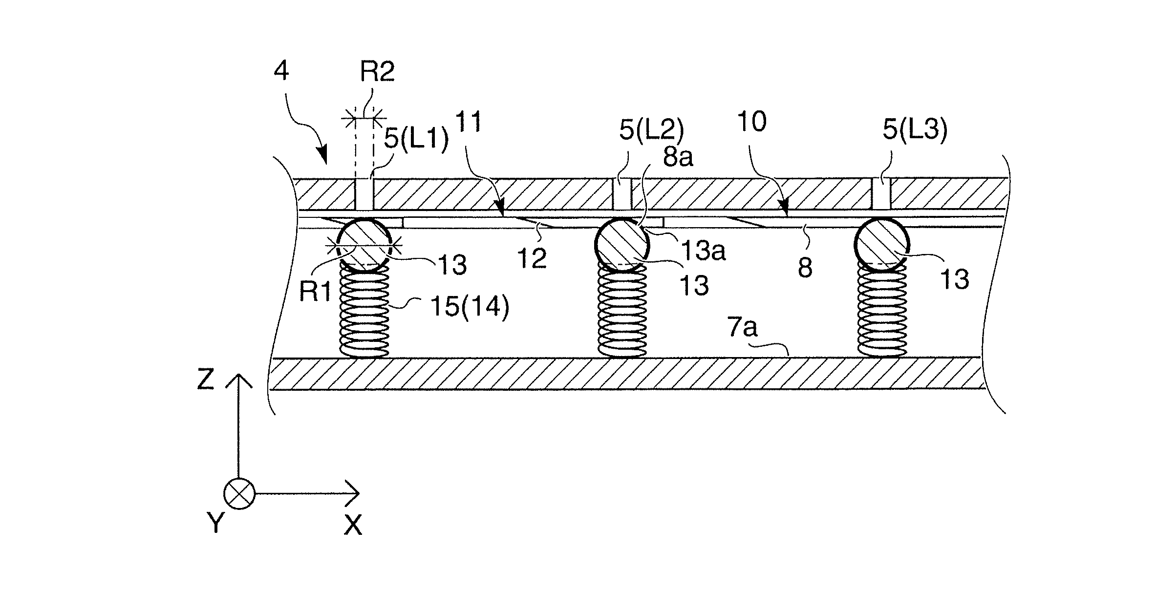
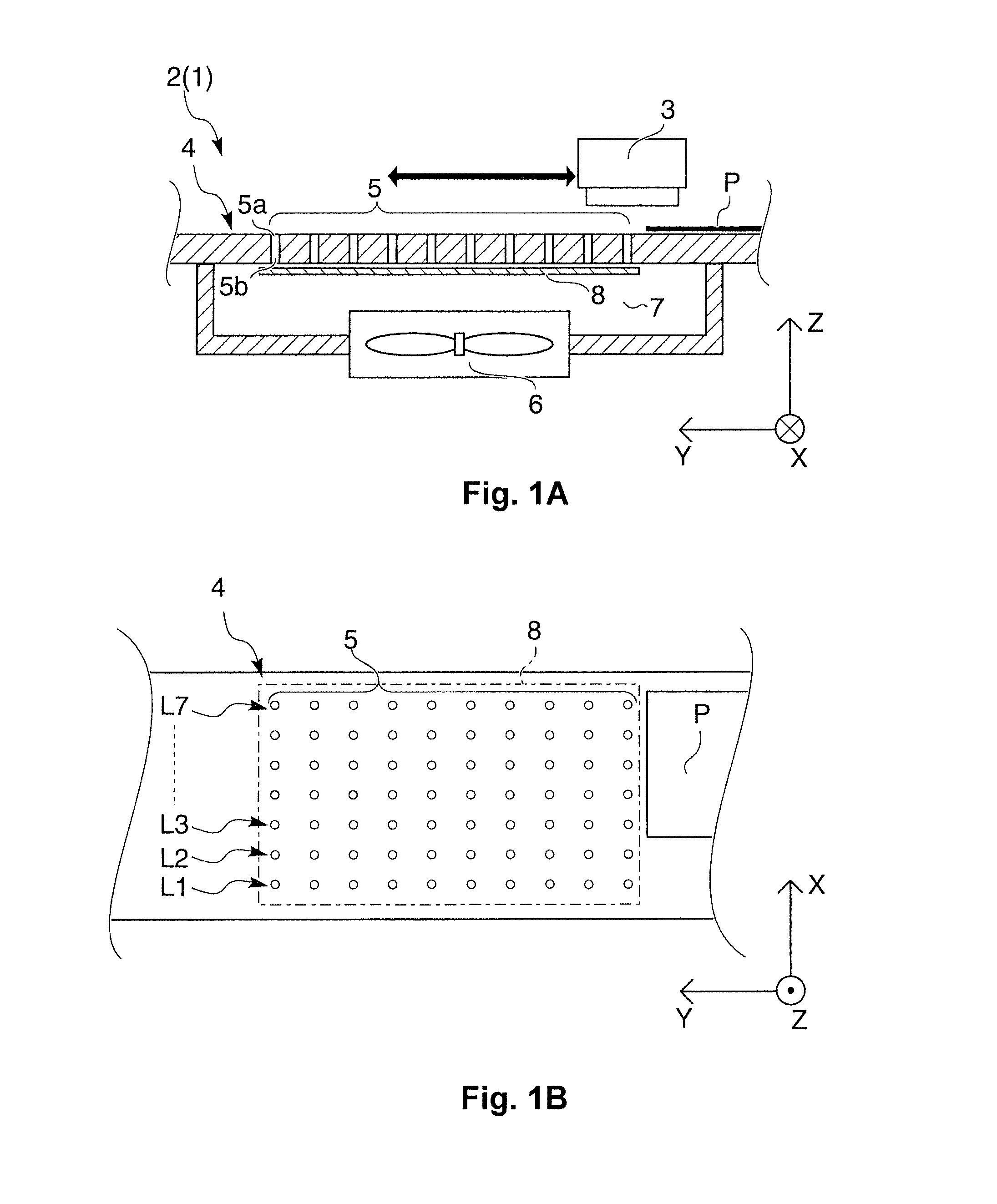
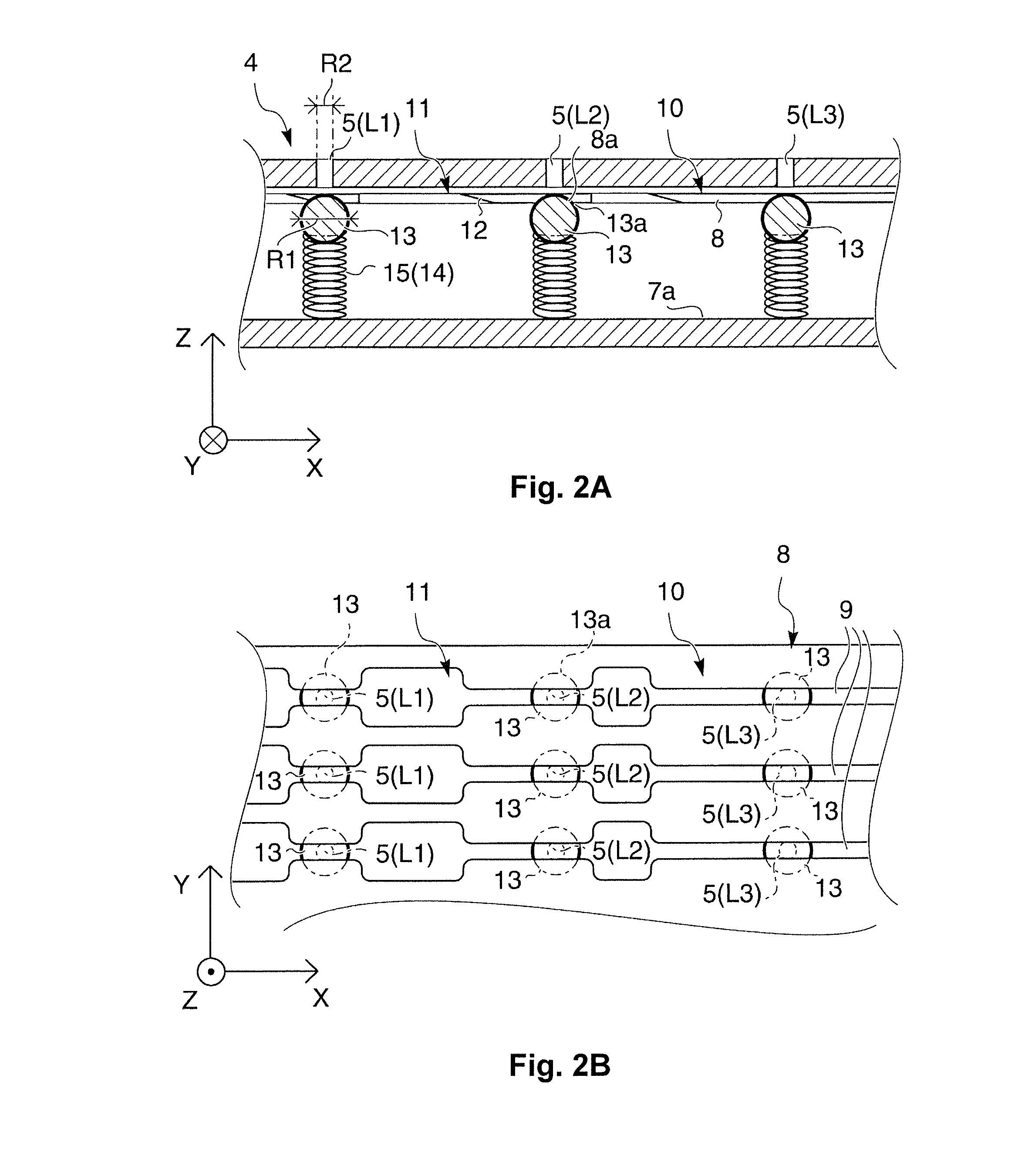
[0010]According to the first aspect of the present invention, the closing members and the sliding member are separate members. Therefore, in a state in which the closing members have closed the holes, the positions of the closing members are not affected even when the suction force from the suction unit acts on the sliding member. The airtightness in the closed state can thereby be improved. As a result, there is no risk of a loss of suction force via the holes in the opened state. Specifically, the recording medium can be efficiently held by suction on the medium support part within a range that faces the holes selected for the opened state.
[0021]According to the fifth aspect of the present invention, in addition to the same operational effects as any of the first through fourth aspects, it is possible to stabilize the relative positional relationship between the holes and the closing members in a direction orthogonal to the movement direction of the closing members. Since the closing members are spherical, the closed state can be enacted readily even when the orientations and alignments of the closing members have changed.

Problems solved by technology

Therefore, there arises a risk that it will be difficult to slide the shutter.
There is particularly a risk in cases in which sliding is done manually.

Method used


Image

  • Recording device
  • Recording device
  • Recording device

Examples


other embodiment 1

[0083]FIG. 5A is a schematic side view showing the opened and closed states of the holes according to another embodiment 1.

[0084]In the other embodiment 1 as shown in FIG. 5A, guide parts are provided for guiding the closing members in a direction away from the holes.

[0085]Since the other components are identical to those of the embodiment previously described, the same symbols are used and descriptions thereof are omitted.

[0086]Guide parts 20 are formed into cylindrical shapes whose axes are in the Z-axis direction. The closing members 13 and the compression coil springs 15 are placed inside the cylindrical shapes. The inside surfaces 21 of the cylindrical shapes of the guide parts 20 are configured so as to be capable of guiding the closing members 13. Tapering second inclined parts 22 are formed in the sides of the inside surfaces 21 near the holes 5. When a switch is made to the closed state, the second inclined parts 22 can thereby guide the closing members 13 to positions faci...

other embodiment 2

[0091]FIG. 5B is a schematic plan view showing the shapes of the grooves of the sliding member according to another embodiment 2. To make FIG. 5B easier to understand, the surface supporting the paper in the medium support part, which is the top surface side of the negative pressure chamber, is not shown.

[0092]A sliding member 30 according to the other embodiment 2 has third inclined parts 31 in the vicinities of the borders between the first areas 10 and the second areas 11, as shown in FIG. 5B.

[0093]Since the other components are identical to those of the embodiment previously described, the same symbols are used and descriptions thereof are omitted.

[0094]In the third inclined parts 31, the distal end sides in the sliding direction of the sliding member 30 when the holes 5 are switched from the closed state to the opened state are provided so that the grooves 9 increase in width.

[0095]Therefore, the same operational effects as those of the first inclined parts 12 of the embodiment...


PUM


Abstract

A recording device includes a plurality of holes formed in the medium support part, a suction unit configured to suck out air via the holes, closing members configured and arranged to move in a direction away from the holes, an urging unit configured to urge the closing members toward the holes, and a sliding member configured and arranged to slide in a direction intersecting a moving direction in which the closing members move. The sliding member is configured and arranged to contact the closing members, and by sliding the sliding member, at least one hole is switched between a state in which the hole is closed by the closing member and a state in which the hole is left open by the closing member.

Description

CROSS-REFERENCE TO RELATED APPLICATIONS[0001]This application claims priority to Japanese Patent Application No. 2010-090164 filed on Apr. 9, 2010. The entire disclosure of Japanese Patent Application No. 2010-090164 is hereby incorporated herein by reference.BACKGROUND[0002]1. Technical Field[0003]The present invention relates to a recording device comprising a medium support part for supporting a recording medium, a plurality of holes whose one end sides are formed in the side of the medium support part that supports the recording medium, and suction unit which are provided to the other end sides of the holes and which suck out the air over the medium support part via the holes.[0004]In the present application, the term “recording device” includes inkjet printers, wire dot printers, laser printers, line printers, copy machines, fax machines, and other types of devices.[0005]2. Related Art[0006]In conventional practice, as shown in Japanese Laid-Open Patent Publication No. 2002-205...

Claims


Application Information

Patent Timeline
Patent Type & Authority Patents(United States)
IPC IPC(8): B65H5/02
CPCB41J11/0085B41J11/06B65H5/222B65H2801/12B65H2406/351B65H2406/363
Inventor YAMADA, JUN
Owner SEIKO EPSON CORP
Why Eureka
Try Eureka