Fastening device with tolerance compensation

a technology of tolerance compensation and fastening device, which is applied in the direction of washers, screws, couplings, etc., can solve the problems of blind rivets and relative cost, and achieve the effects of high connection strength, simple and easy production, and markedly more cost-effective production

Active Publication Date: 2011-11-29
BOLLHOFF VERBINDUNGSTECHNIK GMBH
View PDF15 Cites 39 Cited by
  • Summary
  • Abstract
  • Description
  • Claims
  • Application Information

AI Technical Summary

Benefits of technology

[0008]A substantial advantage of the fastening device configured according to the invention is that it is made up of individual parts which are geometrically particularly simple. The blind rivet nut and the threaded adjusting nut may be standard fastening elements. The threaded sleeve and the locating plate of the adjusting unit are elements which are simple and easy to produce. The retainer and the driving bush which do not have to transmit any fastening forces, may be produced from plastic and produced, for example, by injection moulding. Although the fastening device consists of a larger number of individual parts, therefore, it may be produced markedly more cost effectively than the fastening device of the aforementioned DE 101 51 383.
[0009]Moreover, by the specific choice of material of the individual parts transmitting the fastening forces, a high connecting strength may be achieved. In a further embodiment of the invention, the blind rivet nut and the threaded adjusting nut of the base unit as well as the threaded sleeve and the locating plate of the adjusting unit are produced from a metallic material, in particular steel. In this manner, with the fastening device configured according to the invention, a connecting strength of strength class 8 may be easily achieved.

Problems solved by technology

However, it is relatively costly as the blind rivet nuts are complicated components which are costly in production, due to the two threads of different thread directions and, in particular, the adjusting bush with the resilient fingers.

Method used


Image

  • Fastening device with tolerance compensation
  • Fastening device with tolerance compensation
  • Fastening device with tolerance compensation

Examples


Embodiment Construction

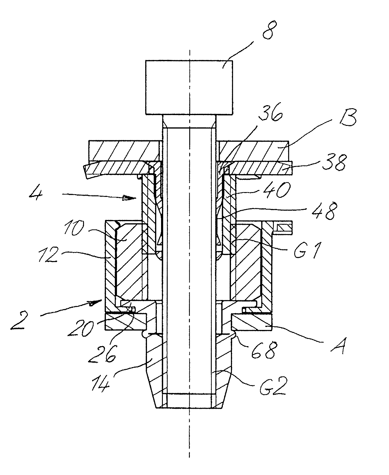
[0022]The fastening device shown in FIGS. 8 and 9 serves to fasten a component B to a component A. The two components A, B have a spacing from one another, which may vary due to tolerances required by the assembly and / or production. The fastening device shown allows an automatic compensation of said tolerances as is described further in more detail.

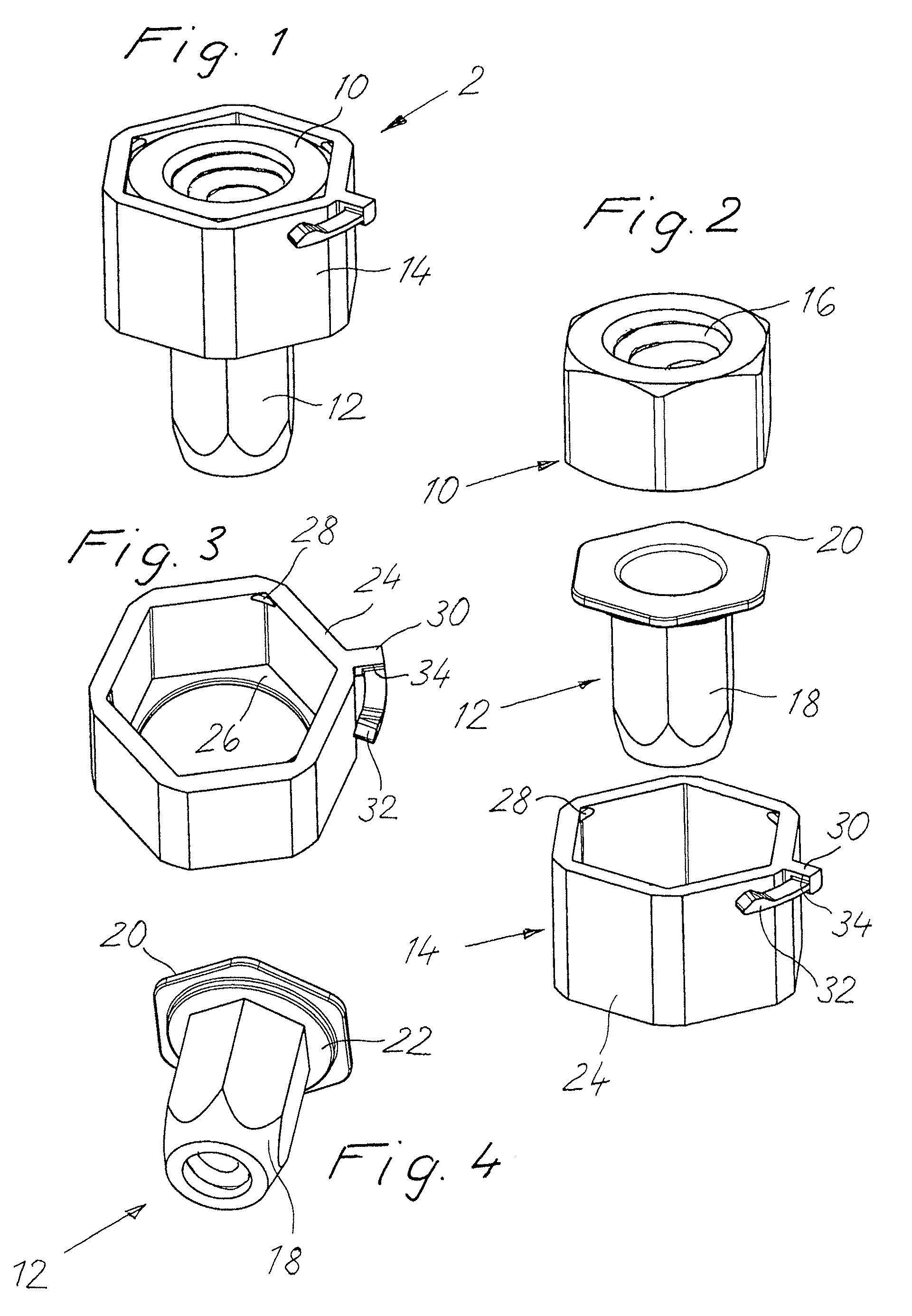
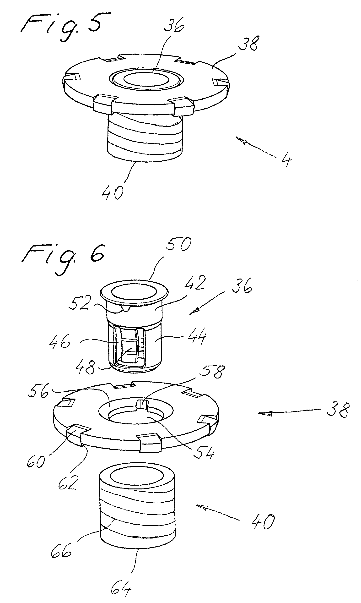
[0023]The fastening device consists of a base unit 2 (FIGS. 1 to 4), an adjusting unit 4 (FIGS. 5, 6) and a fastening screw 8 (FIGS. 8, 9). The base unit 2 and the adjusting unit 4 may be combined to form an assembly unit 6, which is shown in FIG. 7.

[0024]To describe the base unit 2, reference is now made to FIGS. 1 to 4. The base unit 2 consists of a threaded adjusting nut 10, a blind rivet nut 12 and a retainer 14. The threaded adjusting nut 10 is a conventional hexagonal nut which is provided in the embodiment shown, however, with a left-hand internal thread 16.

[0025]The blind rivet nut 12 is a conventional blind rivet nut with a sleev...


PUM


Abstract

A device for fastening components with automatic compensation of tolerances of the spacing therebetween, comprising a base unit including a blind rivet nut securable to one of the components, a threaded adjusting nut and a sleeve-shaped retainer adapted to receive, an adjusting unit including a threaded sleeve, a locating plate and a driving bush connecting the threaded sleeve and the locating plate, the threaded sleeve adapted to be being screwed into the adjusting nut via a first thread pairing of a first thread direction, and a fastening screw which may be screwed into the rivet nut secured to one of the components via a second thread pairing of an opposing second thread direction, forming with the driving bush a releasable connection so that the adjusting unit rotates during rotation of the fastening screw, moving the locating plate into contact with the second component.

Description

CROSS-REFERENCE TO RELATED APPLICATION[0001]This application claims foreign priority benefits of foreign application DE 20 2006 102 493.4, filed Aug. 14, 2006.FIELD OF THE INVENTION[0002]The present invention relates to a fastening device for fastening a component B to a component A with automatic compensation of tolerances in the spacing between the two components.BACKGROUND OF THE INVENTION[0003]Such fastening devices with tolerance compensation are known in large numbers. For example, DE 101 51 383 shows such a fastening device which consists of a base element in the form of a blind rivet nut, an adjusting bush and a fastening screw. The blind rivet nut may be secured to the component A and comprises two axially opposing offset internal threads of which one thread forms, with an external thread of the adjusting bush, a thread pairing of a first thread direction and the other thread forms, with the thread of the fastening screw, a thread pairing of an opposing second thread direct...

Claims


Application Information

Patent Timeline
Patent Type & Authority Patents(United States)
IPC IPC(8): F16B43/02
CPCF16B5/025F16B19/1072Y10T403/125
Inventor FIGGE, HANS ULRICHBURGER, INGO
Owner BOLLHOFF VERBINDUNGSTECHNIK GMBH
Why Eureka
Try Eureka