Electrical tool with a multi-stage gear transmission

a gear transmission and electric tool technology, applied in the field of electric tools, can solve the problem of increasing the height of the electrical tool in the region of the gear transmission housing, and achieve the effect of simplifying the assembly of the tool

Active Publication Date: 2011-11-29
HILTI AG
View PDF1 Cites 9 Cited by
  • Summary
  • Abstract
  • Description
  • Claims
  • Application Information

AI Technical Summary

Benefits of technology

[0009]The foregoing novel features of the present invention provide, on each of the connection element, a rocker-like region. The rocker-like region enables application to a respective connection element, opposite torques by application of unidirectional shifting forces with a time offset thereto. Thereby, by displacing the shifting slide, the tracing profile can be reciprocated, between different shifting positions, despite an action, in all of the shifting positions, of a one-sides restrain with respect to the shifting forces. This means that shifting between the shifting positions is effected either by pure pressure or by a mere tensioning. Thereby, the shifting slide can be formed as a compact part, without opening and, in particular, without a control slot, and with one of its outer side forming the tracing profile. In this way, the headroom of the shifting slide in the gear transmission housing can be noticeably reduced.
[0014]Advantageously, the support sections are fixedly secured in the support receptacles. This provides for securing of the connection elements on the gear transmission housing, simplifying the assembly of the tool.

Problems solved by technology

The shifting slide requires, because of control slot formed therein, a certain headroom in the gear transmission housing and because of it, a certain space, which leads to an increase of the heights of the electrical tool in the region of the gear transmission housing.

Method used


Image

  • Electrical tool with a multi-stage gear transmission
  • Electrical tool with a multi-stage gear transmission
  • Electrical tool with a multi-stage gear transmission

Examples


Embodiment Construction

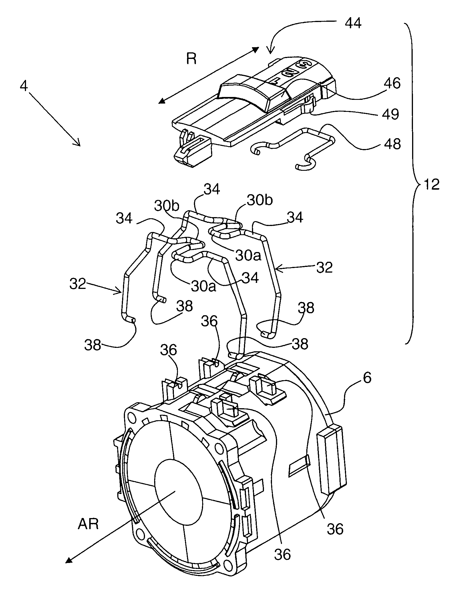
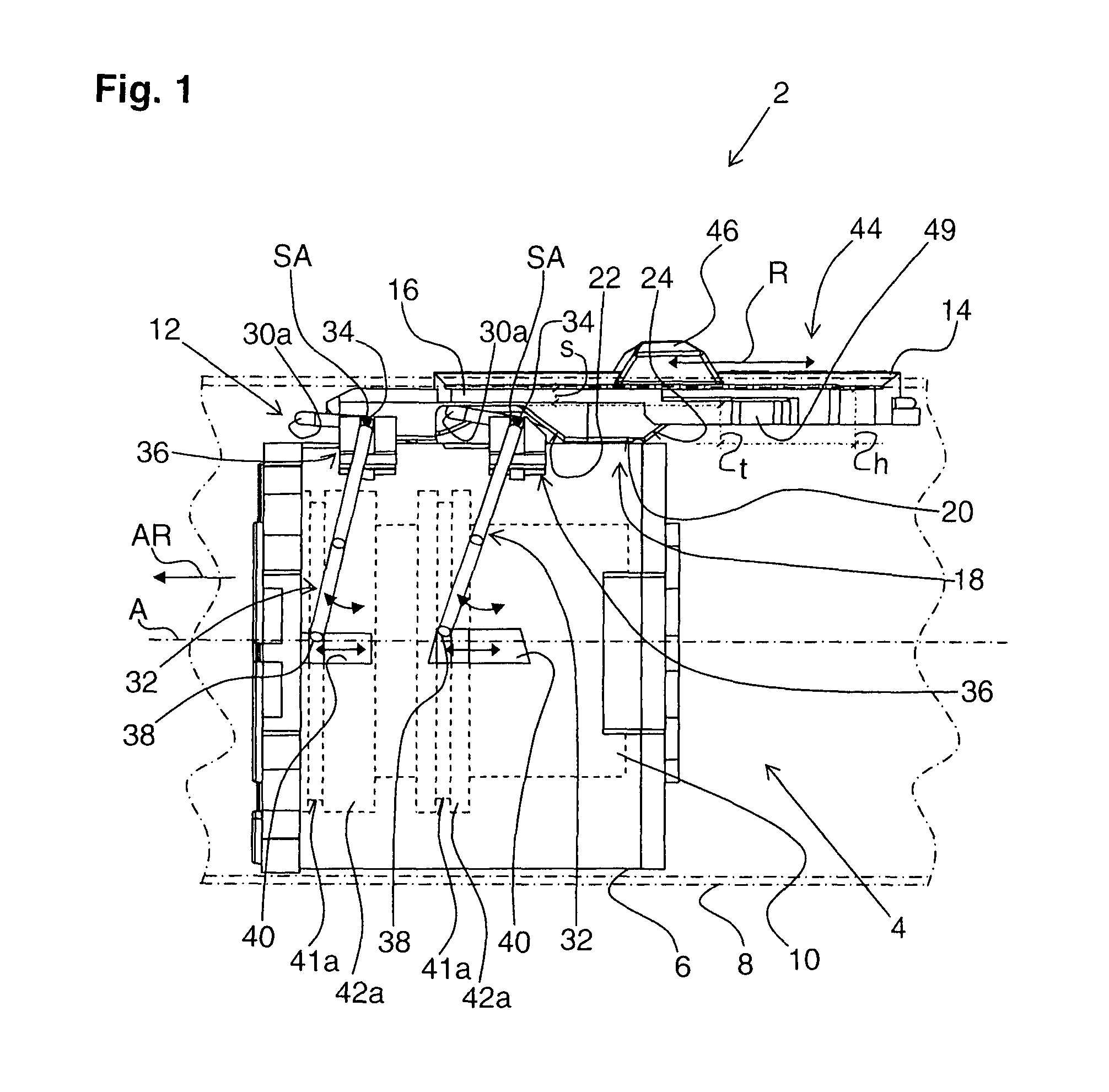
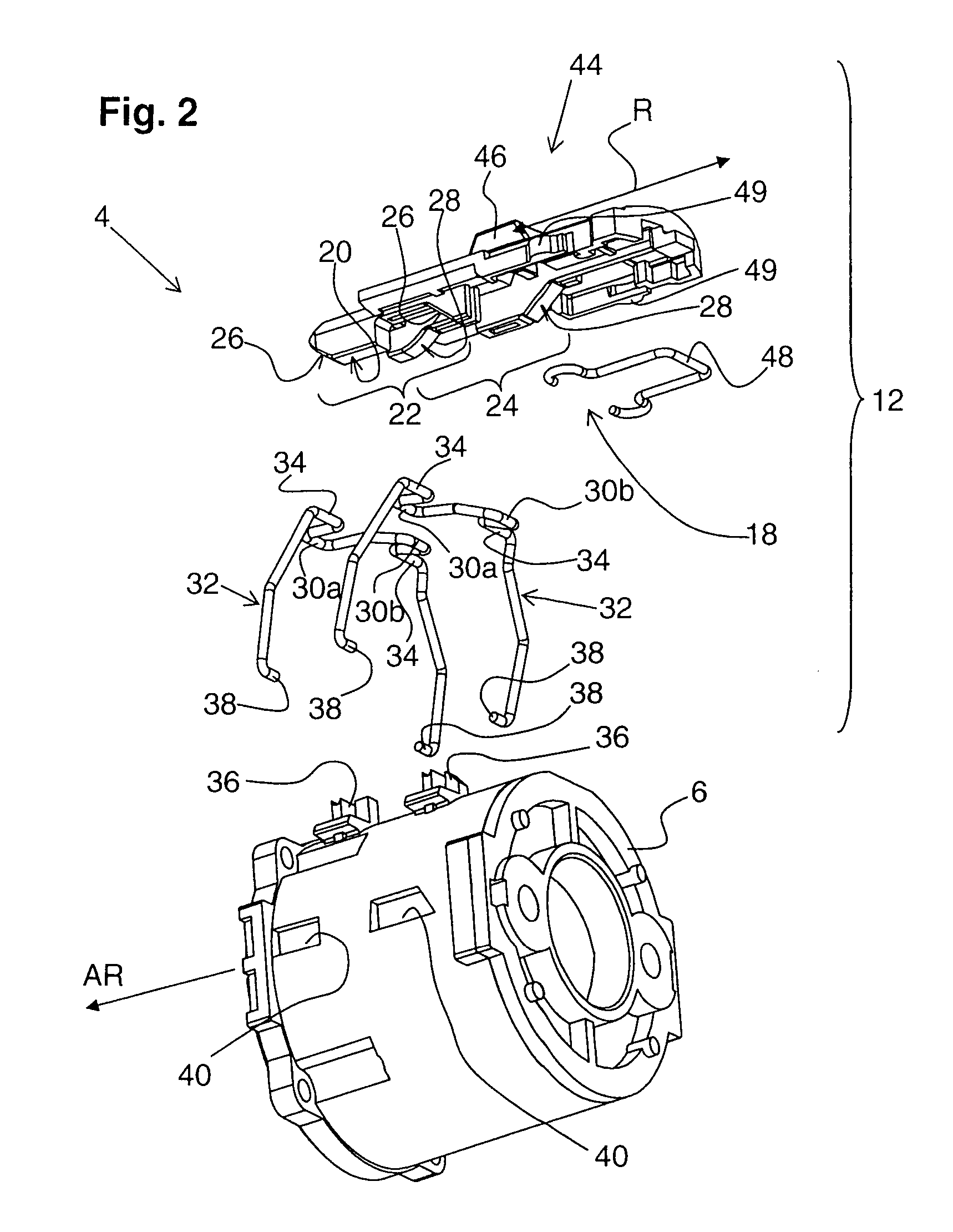
[0023]FIG. 1 shows, as discussed above, an electrical tool 2 according to the present invention at a height of a gear driving mechanism 4. The electrical tool 2 can be formed as a screwdriving tool or as a drilling tool. The gear driving mechanism 4 has a gear housing 6 arranged in a tool housing 8. A schematically shown, gear transmission 10, which has three shift stages, is located in the gear housing 6.

[0024]For shifting the gear transmission 10 between the three shift stages, there is provided a shifting device generally designated with a reference numeral 12. The shifting device 12 has a shifting slide 14 displaceable relative to the tool housing 8 in direction R. The direction R is directed parallel to the operational direction AR along an operational axis A of the electrical tool 2. On the shifting slide 14, there are formed rib-shaped guide means 16 that cooperates with guide counter means, not shown in detail, provided on the tool housing 8.

[0025]At its first end 18 adjacen...


PUM


Abstract

An electrical tool includes a multi-stage gear transmission (10) located in the gear transmission housing (6) and having at least two axially displaceable indexing gear (42a, 42b), a shifting device (12) for shifting the gear transmission from one stage to another stage and having a shifting slide (14) linearly displaceable between different shifting positions, and at least two connection elements (32) for connecting the shifting slide (14) with respective indexing gears (42a, 42b), with the shifting slide (14) having a tracing profile (20) having two control tracks (22, 24), and the connection elements each having a first and second tracing sections (30a, 30b) to which the tracing profile (20) applies a shifting force in stages and which are arranged on opposite sides of a pivot axis (SA) of a respective connection element (32).

Description

BACKGROUND OF THE INVENTION[0001]1. Field of the Invention[0002]The present invention relates to an electrical tool, in particular a screwdriving or drilling tool, and including a gear transmission housing, and a multi-stage gear transmission located in the gear transmission housing and having at least two axially displaceable indexing gear. The tool is further provided with a shifting device for shifting the gear transmission from one stage to another stage and having a shifting slide linearly displaceable between different shifting positions, and at least two connection elements that connects the shifting slide with respective indexing gears. The shifting slide has a tracing profile for applying a shifting force to the connection elements for pivoting the connection elements in a plurality of predetermined positions corresponding to the gear transmission stages.[0003]2. Description of the Prior Art[0004]In electrical tools of the type described above, the gear transmission can hav...

Claims


Application Information

Patent Timeline
Patent Type & Authority Patents(United States)
IPC IPC(8): F16H3/44
CPCB25F5/001Y10T74/20018Y10T74/2014
Inventor SPIELMANN, DAVIDGERSCHWILER, OTHMARBREITENMOSER, ARMINBREITENMOSER, LEGAL REPRESENTATIVE, REMO
Owner HILTI AG
Why Eureka
Try Eureka