
Refrigerator

a technology of refrigerator and refrigerator, which is applied in the field of refrigerators, can solve the problems of reducing the the above mentioned double-door refrigerator inevitably undergoes a reduction in the volume of the freezing compartment and the refrigerating compartment, and it is difficult to ensure the smooth circulation of air within the machine room. , to achieve the effect of reducing the size of the machine room and enlarged the inner volume of the cooling compartmen

Inactive Publication Date: 2011-12-06
LG ELECTRONICS INC
View PDF23 Cites 1 Cited by
  • Summary
  • Abstract
  • Description
  • Claims
  • Application Information

AI Technical Summary

Benefits of technology

The present invention provides a refrigerator with a reduced machine room size, which results in a larger cooling compartment inner volume. The refrigerator includes a body with multiple cooling compartments separated by a partition, and a machine room located below one of the cooling compartments. The machine room contains necessary elements to operate the cooling compartments. The technical effects of the invention include improved efficiency of the refrigeration cycle and reduced energy consumption.

Problems solved by technology

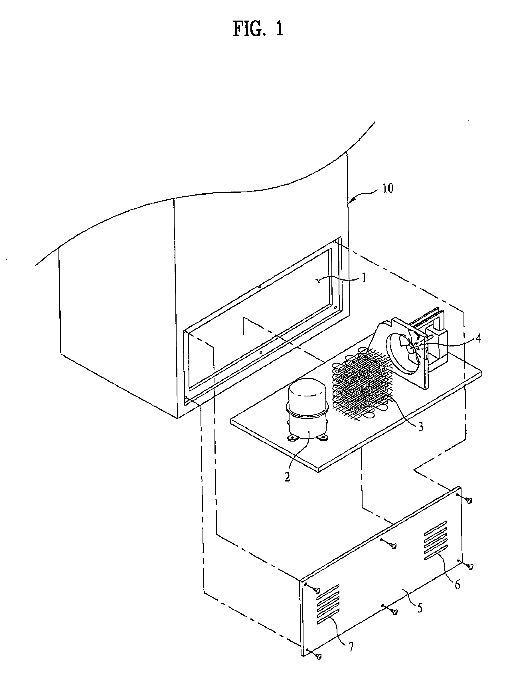
The related art machine room having the above described configuration, however, has a problem of occupying a significantly large area in the refrigerator, and thus reducing the volume of the cooling compartments.
Moreover, the above mentioned double-door refrigerator inevitably undergoes a reduction in volume in both the freezing compartment and the refrigerating compartment.
Therefore, it is difficult to assure the smooth circulation of air within the machine room 1.
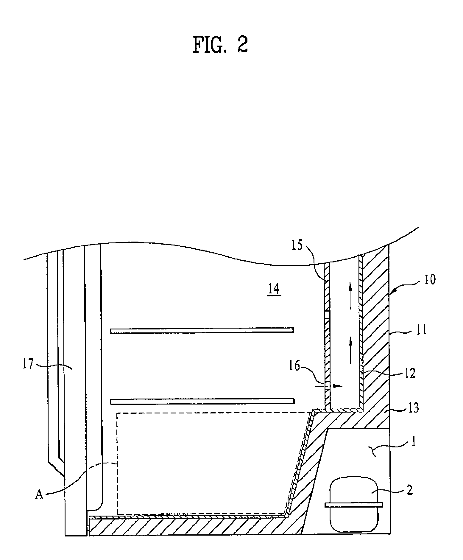
However, because the volume of the space A is limited due to the volume of the machine room 1, and in particular, the lower end of the space A is located at a long distance from the cold air suction hole 16, the related art refrigerator has a problem in that the cold air within the cooling compartment 14 stagnates in the space A, and thus fails to circulate smoothly in the cooling compartment 14.
To solve the above described problems, the space A may be reduced or eliminated, but this method excessively increases the volume of the machine room 1, and on the other hand, excessively decreases the inner volume of the cooling compartment.

Method used


Image

  • Refrigerator
  • Refrigerator
  • Refrigerator

Examples


Embodiment Construction

[0031]Reference will now be made in detail to the preferred embodiments of the present invention, examples of which are illustrated in the accompanying drawings. Wherever possible, the same reference numbers will be used throughout the drawings to refer to the same or like parts.

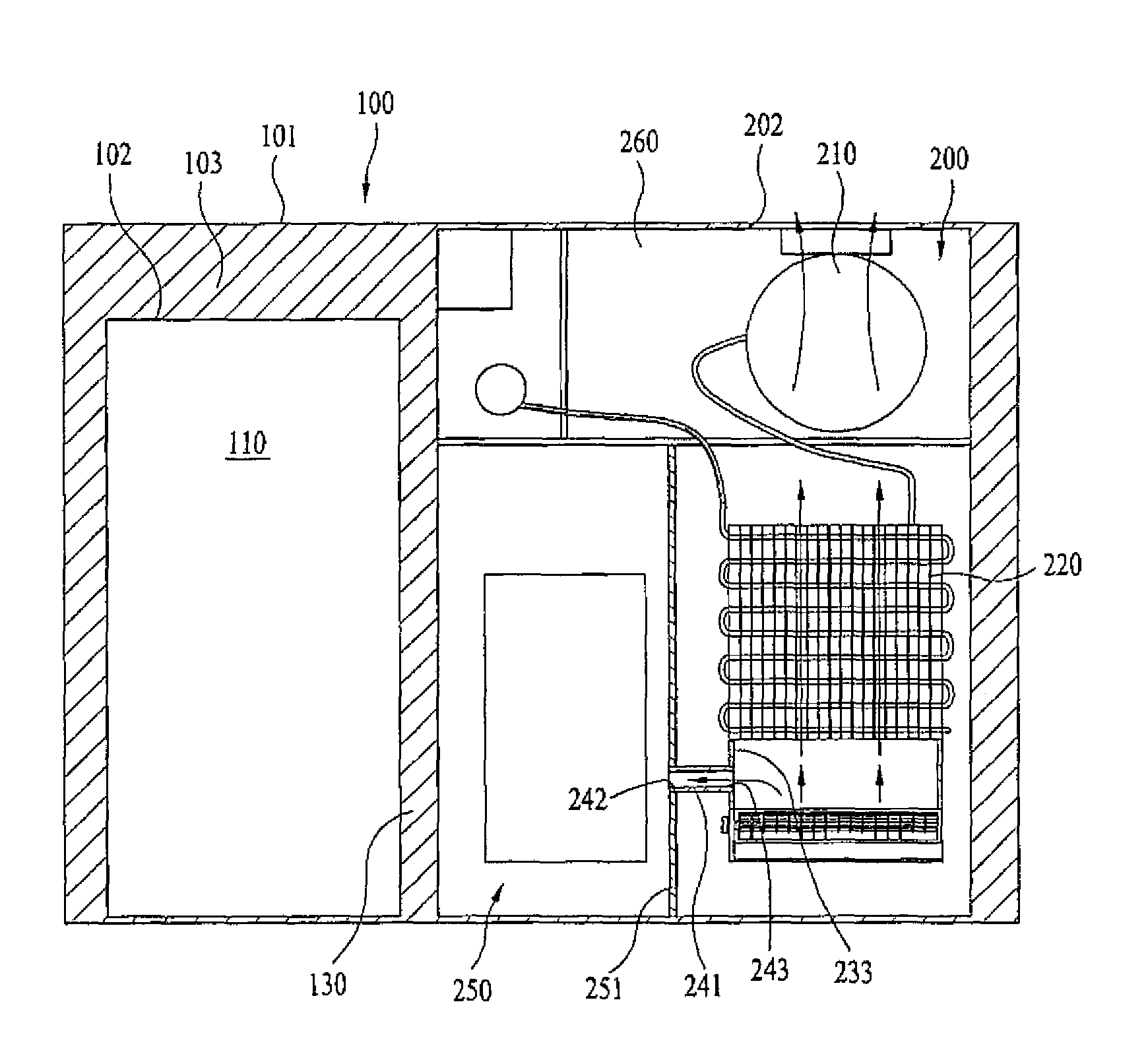
[0032]FIG. 3 illustrates a refrigerator according to an embodiment of the present invention. As shown in FIG. 3, the refrigerator includes a body 100 serving as the overall shell of the refrigerator, and a machine room 200 including a compressor 210. FIGS. 5, 6, 8 and 9 illustrate a first cooling compartment 110, and FIGS. 4 and 7 illustrate a second cooling compartment 120 defined in the body 100. The machine room 200 is provided only in a lower region of the second cooling compartment 120.

[0033]That is, as shown in FIGS. 5, 6, 8 and 9 the first cooling compartment 110 has no machine room, and can achieve an increment in inner volume of up to the volume of the machine room 200. Also, according to embodiment...


PUM


Abstract

A refrigerator including a body having a plurality of cooling compartments separated from each other by a partition, and a machine room defined by the partition in a lower region of one of the plurality of cooling compartments. The machine room receives predetermined elements required to operate the cooling compartments.

Description

CROSS REFERENCE TO A RELATED APPLICATION[0001]This application claims the benefit of the Korean Patent Application No. 10-2007-0069743 filed on Jul. 11, 2007, which is hereby incorporated by reference as if fully set forth herein.BACKGROUND OF THE INVENTION[0002]1. Field of the Invention[0003]The present invention relates to a refrigerator, and more particularly to a refrigerator, in which the size of a machine room is reduced without a degradation in the efficiency of a refrigeration cycle, resulting in an enlarged volume of a cooling compartment.[0004]2. Discussion of the Related Art[0005]Generally, a refrigerator includes cooling compartments, such as a refrigerating compartment and a freezing compartment, and maintains food, etc. stored in the cooling compartments at a low temperature for a long time by supplying cold air into the cooling compartments. Further, the cold air is generated by a refrigeration cycle apparatus including a compressor, a heat exchanger, etc.[0006]The re...

Claims


Application Information

Patent Timeline
Patent Type & Authority Patents(United States)
IPC IPC(8): F25D11/00
CPCF25D23/003F25D2323/00264F25D2323/0022F25D2323/00282F25D29/005F25D2323/00271F25D2321/1442F25D17/04F25D19/00
Inventor CHO, NAM SOOLEE, YOUN SEOKKIM, KYEONG YUNCHAE, SU NAMLEE, JANG SEOK
Owner LG ELECTRONICS INC
Learn More