Pillow block bearing assembly for compound bows

a compound bow and bearing technology, applied in the direction of spring guns, white arms/cold weapons, weapons, etc., can solve the problem that the use of brackets for this purpose is thought to affect the performance of the bow

Active Publication Date: 2011-12-06
BOWTECH INC
View PDF17 Cites 25 Cited by
  • Summary
  • Abstract
  • Description
  • Claims
  • Application Information

AI Technical Summary

Benefits of technology

[0017]Importantly, pillow blocks suitable for use in the practice of this invention need be neither massive nor heavy. It is thus possible to gain the advantages of this invention while avoiding the disadvantages of either mounting brackets or bore holes through the limbs.

Problems solved by technology

The use of brackets for this purpose is thought to impact negatively upon bow performance because of the added bracket weight carried by the limb tip under dynamic conditions.

Method used


Image

  • Pillow block bearing assembly for compound bows
  • Pillow block bearing assembly for compound bows
  • Pillow block bearing assembly for compound bows

Examples


Embodiment Construction

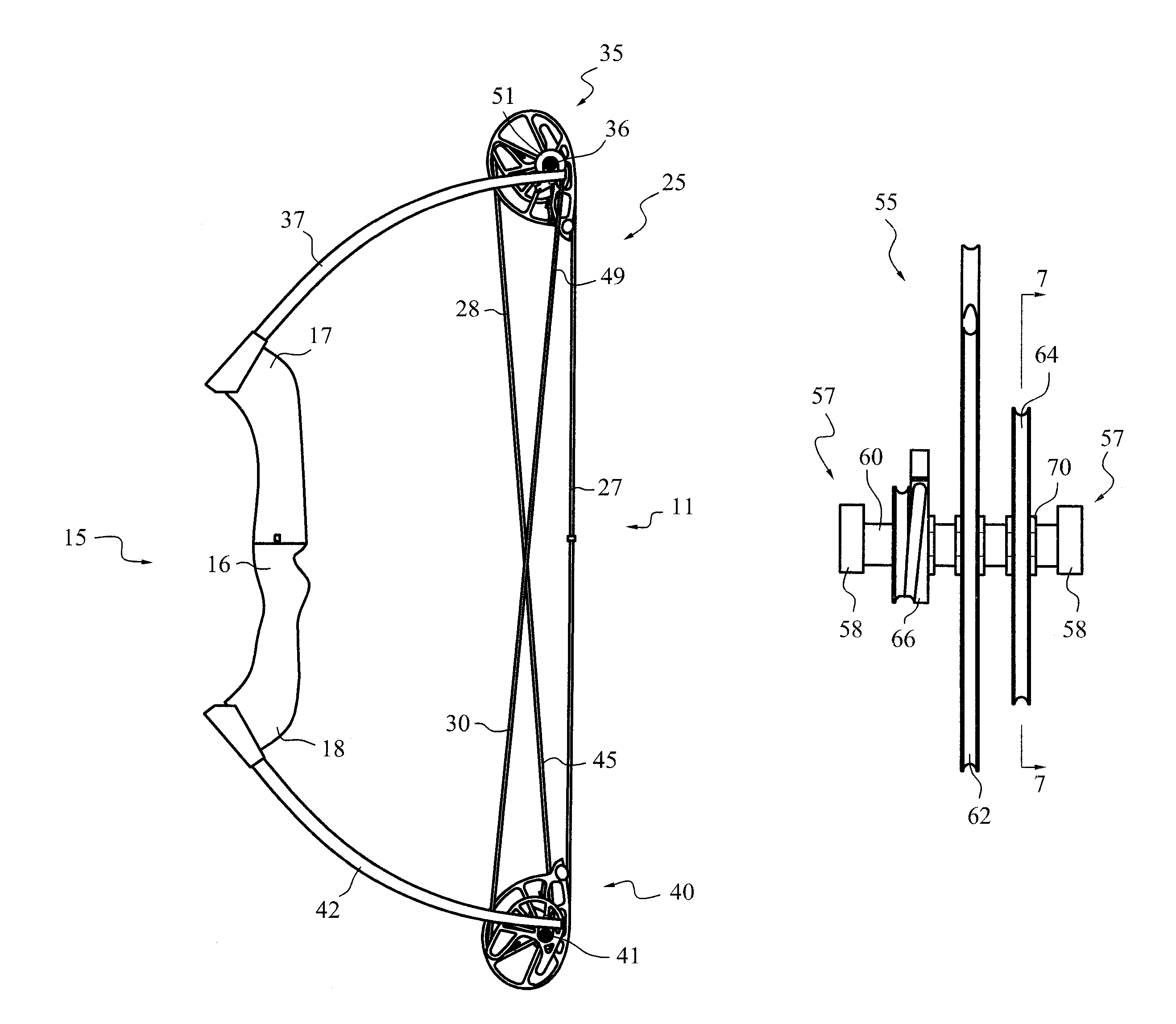
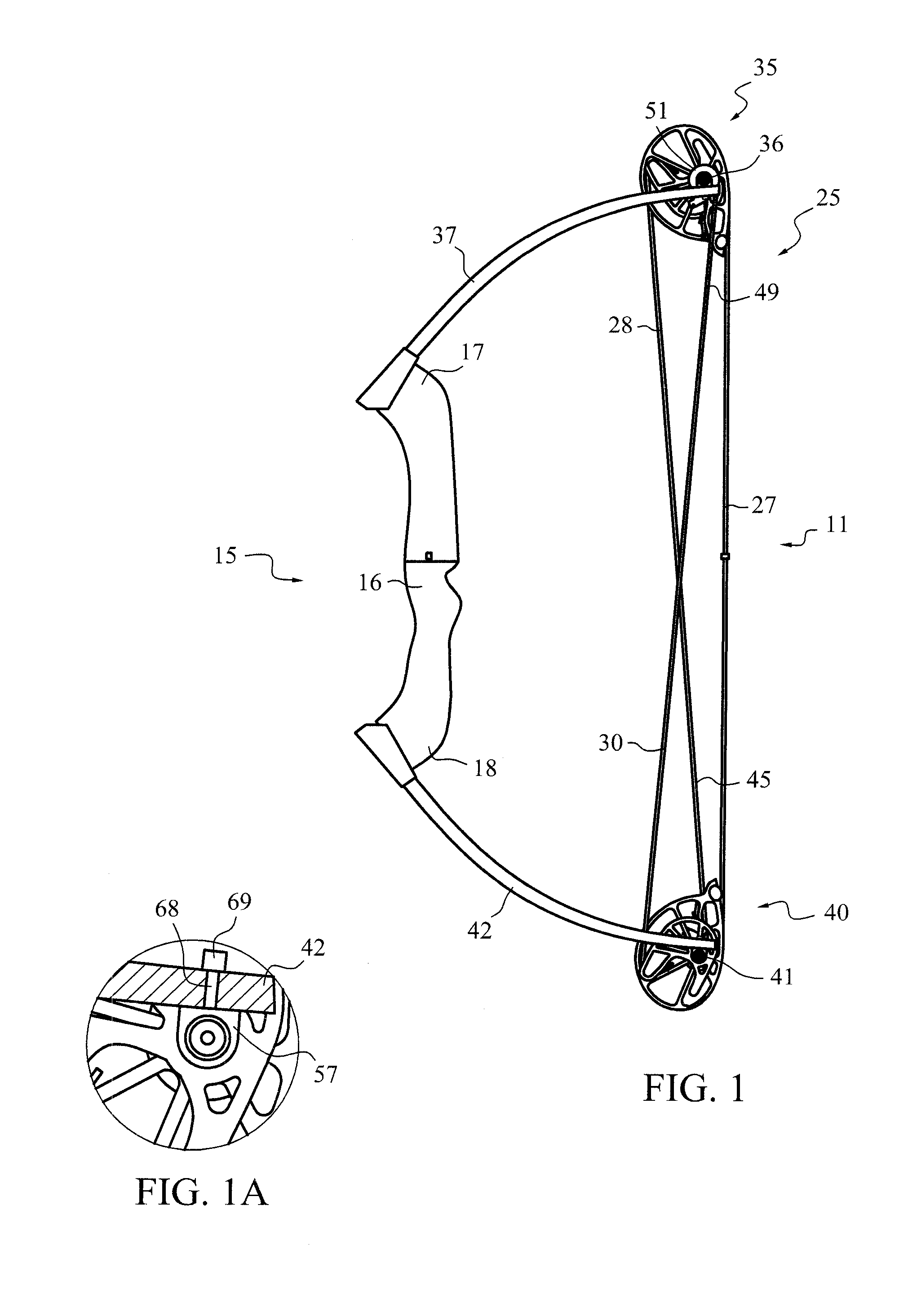
[0037]The compound bow, generally 11, illustrated by FIG. 1, is of generally conventional construction. It includes a handle riser component, generally 15, with a grip 16, an upper end 17 and a lower end 18. The rigging, generally 25, includes a bowstring 27, and two synchronizing cables 28, 30. An upper pulley assembly, generally 35, includes an integral pivot axle 36, mounted at the tip of an upper limb 37. A lower pulley assembly, generally 40 similarly includes an integral pivot axle 41 mounted at the tip of a lower limb 42. The rigging 35 is arranged generally as described by copending U.S. patent application Ser. No. 11 / 241,030, with the synchronizing end 45 of the cable 28 coupled to the pulley assembly 40 through a synchronizing anchor component (not visible). Similarly, the synchronizing end 49 of the cable 30 is coupled to the pulley assembly 35 through a synchronizing anchor component 51. This “cross coupling” configuration, while not required, is a desirable feature for ...


PUM


Abstract

The axles of the eccentric pulley assemblies of a compound bow are journal mounted in pillow blocks carried by the limbs of the bow.

Description

CROSS-REFERENCE TO RELATED APPLICATIONS[0001]This application is a continuation-in-part of U.S. patent application Ser. No. 12 / 074,930, filed Mar. 7, 2008, titled “PULLEY ASSEMBLY AND AXLE FOR COMPOUND BOWS”, the priority of the filing date of which is claimed, and the entire contents of which are hereby incorporated by reference.BACKGROUND OF THE INVENTION[0002]1. Field[0003]This invention relates to compound archery bows. It is particularly directed to an improved bearing assembly for the pulley assemblies of such bows.[0004]2. State of the Art[0005]Compound archery bows commonly carry assemblies of pulley members (usually called “eccentrics” or “cams”) eccentrically mounted on axles in association with respective bow limbs. These limbs extend in opposite directions from a grip (usually comprising a central portion of a handle riser). The rigging for compound bows includes a bowstring trained around the pulley members of the system, the string being received by grooves or other fu...

Claims


Application Information

Patent Timeline
Patent Type & Authority Patents(United States)
IPC IPC(8): F41B5/10
CPCF41B5/10F41B5/105Y10S124/90
Inventor LARSON, MARLOW W.
Owner BOWTECH INC
Why Eureka
Try Eureka