Elevator and traction sheave of an elevator

a technology of traction sheave and elevator, which is applied in the field of elevator, can solve the problems of corrosion of steel wire ropes and the friction coefficient of metallic traction sheave used in elevators, insufficient in itself to maintain the required grip, and damage to coatings, etc., and achieves excellent grip. , the effect of reducing ropes

Inactive Publication Date: 2011-12-06
KONE CORP
View PDF67 Cites 13 Cited by
  • Summary
  • Abstract
  • Description
  • Claims
  • Application Information

AI Technical Summary

Benefits of technology

[0009]It is an object of the invention to achieve an elevator in which the traction sheave has an excellent grip on a steel wire rope and in which the traction sheave is durable and of a design that reduces rope wear. Another object of the invention is to eliminate or avoid the above-mentioned disadvantages of prior-art solutions and to achieve a traction sheave that provides an excellent grip on the rope and is durable and reduces rope wear. A specific object of the invention is to disclose a new type of engagement between the traction sheave and the rope in an elevator. It is also an object of the invention to apply said engagement between the traction sheave and the rope to possible diverting pulleys of the elevator.

Problems solved by technology

The coefficient of friction between the steel wire ropes and the metallic traction sheaves used in elevators is often insufficient in itself to maintain the required grip between the traction sheave and the hoisting rope in normal situations during elevator operation.
External wear of the rope consists of the wear of surface wires mainly caused by the traction sheave.
The inserts undergo wear caused by the forces imposed on them by the ropes, so they have to be replaced at intervals.
As such compression causes lateral spreading of the material, the coating might be damaged by the great tensions produced in it.

Method used


Image

  • Elevator and traction sheave of an elevator
  • Elevator and traction sheave of an elevator
  • Elevator and traction sheave of an elevator

Examples


Embodiment Construction

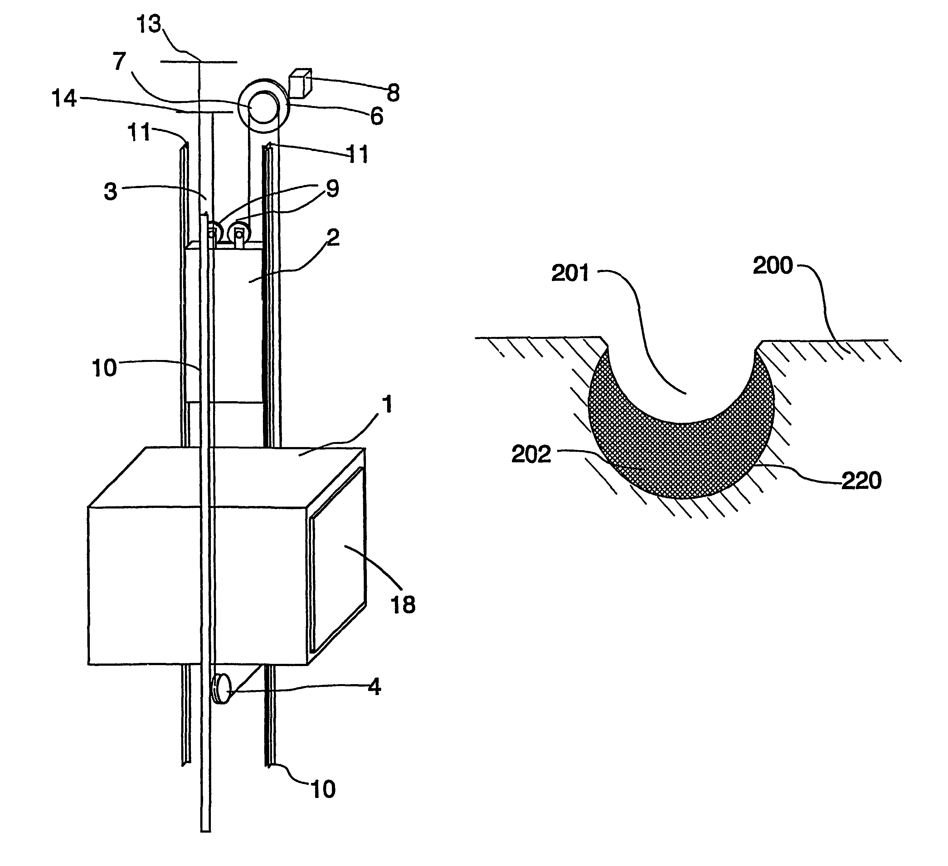
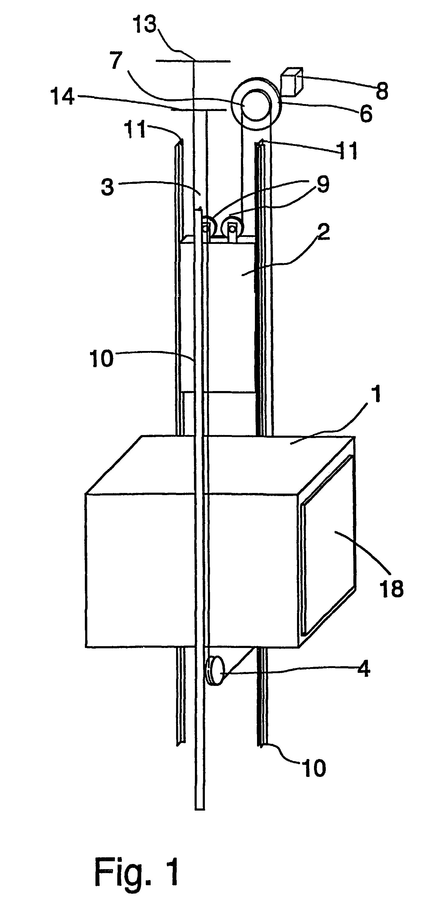
[0031]FIG. 1 is a diagrammatic representation of the structure of an elevator. The elevator is preferably an elevator without machine room, in which the drive machine 6 is placed in the elevator shaft, although the invention is also applicable for use in elevators with machine room. The passage of the hoisting ropes 3 of the elevator is as follows: One end of the ropes is immovably fixed to an anchorage 13 located in the upper part of the shaft above the path of a counterweight 2 moving along counterweight guide rails 11. From the anchorage, the ropes run downward and are passed around diverting pulleys 9 suspending the counterweight, which diverting pulleys 9 are rotatably mounted on the counterweight 2 and from which the ropes 3 run further upward to the traction sheave 7 of the drive machine 6, passing around the traction sheave along rope grooves on the sheave. From the traction sheave 7, the ropes 3 run further downward to the elevator car 1 moving along car guide rails 10, pas...


PUM


Abstract

An elevator may include an elevator car, a counterweight, a set of hoisting ropes, and one or more rope pulleys. The car and counterweight may be suspended on the hoisting ropes. At least one rope pulley may include a solid surface including a plurality of rope grooves configured to receive at least one hoisting rope. Each rope groove may generally conform to a semi-circular shape and may include a groove bottom and sides. The at least one rope pulley may include a coating adhesively bonded to it. The coating may directly contact the at least one hoisting rope. A coating thickness may be less than or equal to about 3 mm. At the groove bottom of each rope groove, the coating thickness may be substantially less than half a thickness of the at least one hoisting rope. The coating may cover the groove bottom and sides of each rope groove.

Description

CROSS-REFERENCE TO RELATED APPLICATIONS[0001]This application is a continuation application under 37 C.F.R. §1.53(b) of PCT International Application No. PCT / FI01 / 01072 filed on Dec. 7, 2001, which claims the benefit under 35 U.S.C. §119(a) of Finnish Patent Application 20002701 filed Dec. 8, 2000, the entire contents of each of which are hereby incorporated by reference.BACKGROUND[0002]1. Field[0003]The present invention relates to an elevator, as discussed below, and to an elevator traction sheave, as also discussed below.[0004]2. Description of Related Art[0005]The operation of a conventional traction sheave elevator is based on a solution in which steel wire ropes serving as hoisting ropes and also as suspension ropes are moved by means of a metallic traction sheave, often made of cast iron, driven by an elevator drive machine. The motion of the hoisting ropes produces a motion of a counterweight and elevator car suspended on them. The tractive force from the traction sheave to ...

Claims


Application Information

Patent Timeline
Patent Type & Authority Patents(United States)
IPC IPC(8): B66B11/08F16H27/02B66B7/00B66D3/04B66B7/06D07B1/06
CPCB66B7/06Y10T74/18848B66B15/04
Inventor AULANKO, ESKOMUSTALAHTI, JORMARANTANEN, PEKKAMAKIMATTILA, SIMO
Owner KONE CORP
Why Eureka
Try Eureka