Clay extruder

a technology of extruder and clay, which is applied in the field of clay extruder, can solve the problems of generating various formed article defects, forming defects of honeycomb structures, and affecting the quality of clay, so as to reduce the friction in the face where the rectifying rotary blade comes in contact with clay, and reduce the risk of device failure

Active Publication Date: 2011-12-06
NGK INSULATORS LTD
View PDF12 Cites 1 Cited by
  • Summary
  • Abstract
  • Description
  • Claims
  • Application Information

AI Technical Summary

Benefits of technology

[0022]According to the clay extruder of the above constitution [1], on the extrusion port side of the clay extruder, the screw has the rectifying portion including the rectifying rotary blade. Moreover, the rectifying rotary blade is provided so that the angle formed between the face on the extrusion port side in the sectional shape of the rectifying rotary blade cut along the plane extending along the central line of the rotary shaft and the central line of the rotary shaft gradually decreases, as the rectifying rotary blade comes close to the extrusion port. In consequence, it is possible to decrease a problem that a density difference is generated in the clay and the clay becomes uneven owing to the thrust force of the rotary blade. When the angle between the rectifying rotary blade and the central line of the rotary shaft is decreased, the curving of a flow pattern in the columnar article can be decreased.
[0024]According to the above constitution [3], the sectional shapes of the rectifying rotary blade members cut along the direction vertical to the rotary shaft are rotationally symmetrical with respect to the central line of the rotary shaft. In consequence, the flow patterns due to the density difference of the columnar article are rotationally symmetrical. Moreover, since the rectifying rotary blade members are rotationally symmetrically arranged, it is possible to decrease the risk of device failure due to contact between the rotary blade and the drum owing to the eccentricity of the rotary blade during the thrusting of the clay.
[0025]According to the above constitution [4], the rectifying rotary blade is provided so that the sectional shape of the rectifying rotary blade cut along the direction vertical to the rotary shaft is gradually reduced outwardly in the diametric direction of the drum, and expands along the inner wall of the drum, as the rectifying rotary blade comes close to the extrusion port. Therefore, in the sectional shape of the rectifying rotary blade cut along the direction vertical to the rotary shaft, a region where the rectifying rotary blade shears the clay in the drum decreases, and the density unevenness can be decreased.
[0026]According to the above constitution [5], the rectifying rotary blade is provided so that the sectional shape of the rectifying rotary blade cut along the direction vertical to the rotary shaft is gradually reduced outwardly in the diametric direction of the drum, and expands along the inner wall of the drum, as the rectifying rotary blade comes close to the extrusion port, and so that the sectional shape becomes circular arc in the extrusion port. Therefore, friction in the face where the rectifying rotary blade comes in contact with the clay decreases, and the forming properties of the columnar article can be improved.
[0027]According to the above constitution [6], the volume of the clay fed under pressure to the extrusion port is kept at a constant level for one cycle of the rotation of the rectifying rotary blade in a range of 5 to 30 cm from the end of the extrusion port. In consequence, it can be prevented that the clay is starved at the tip of the rectifying rotary blade, is laminated in the screw and generates a clay coarse portion. In the range of 0 to 5 on from the end of the extrusion port, the clay is substantially columnar, and the clay hardly needs to be fed under pressure or rectified in this range.
[0028]According to the clay extruder of the present invention, the unevenness of the clay density during the rotation of the screw in the clay extruder can be prevented to obtain a satisfactory a columnar or a rectangular-columnar article having high homogeneity. Moreover, in a case where the preparation of the columnar article by extrusion forming is performed to obtain the ceramic honeycomb structure, the ceramic honeycomb structure which does not have any defect can easily be manufactured.

Problems solved by technology

In this case, the columnar article is prepared by the clay extruder, but the density of the clay partially becomes uneven by the rotation of the screw of the clay extruder.
Moreover, when a ceramic honeycomb structure is formed by extrusion using the columnar article, various formed article defects are generated.
When the preparation of the ceramic honeycomb structure by the extrusion forming is performed by using the columnar article obtained by the conventional clay extruder having the structure shown in FIG. 2, unevenness is generated in the clay density of the columnar article by the rotation of the screw in the clay extruder, and the forming defect of the honeycomb structure is sometimes generated.
Therefore, when the extrusion forming and the subsequent firing of the ceramic honeycomb structure are performed by using the columnar or columnar rectangular clay article obtained by the conventional clay extruder 30 as shown in FIGS. 2 and 3, the density in the columnar or columnar rectangular clay article is uneven for the above reason, and hence various formed article defects or firing defects might be generated.

Method used


Image

  • Clay extruder
  • Clay extruder
  • Clay extruder

Examples


example 1

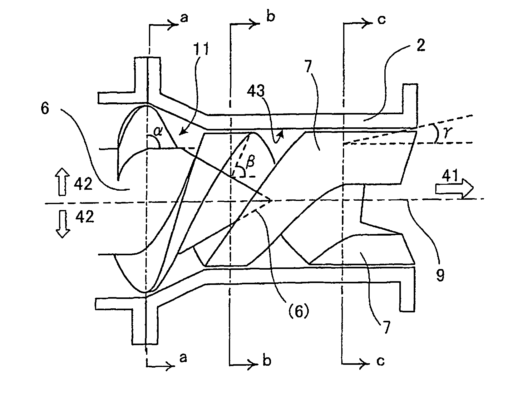
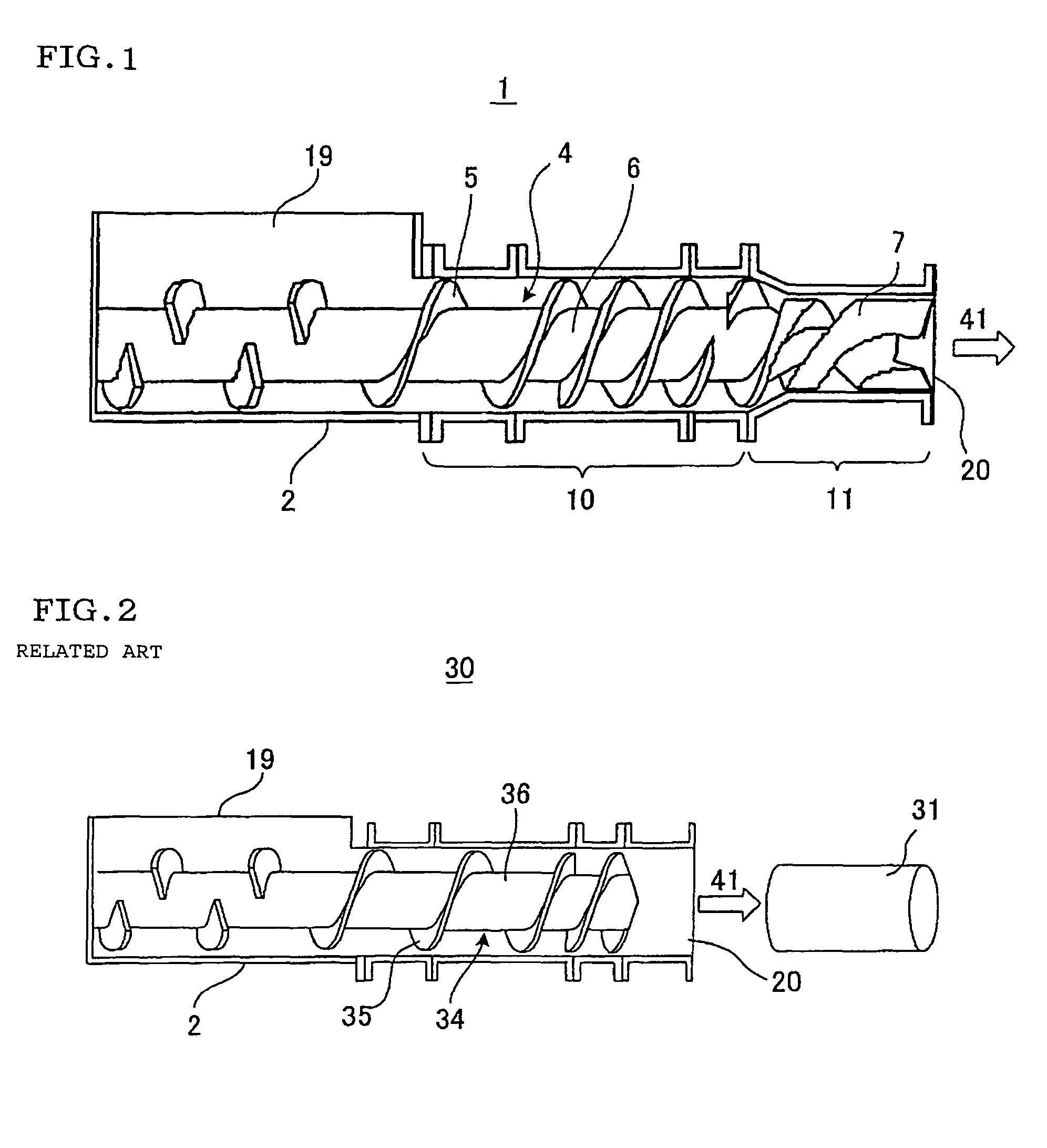
[0072]In the embodiment of the present invention, a columnar or columnar rectangular clay article was prepared by using a clay extruder 1 including a rectifying rotary blade 7 having the above-mentioned shape shown in FIGS. 1, 7. The center of this columnar or columnar rectangular clay article was cut as a test piece 18 in parallel with an extruding direction 41 as shown in FIG. 22, and the cut face of the columnar or columnar rectangular clay article was observed. FIG. 23 shows a schematic side view of the test piece 18 of Example 1. Arrows in FIG. 23 show a diametric direction 14 of the columnar or a rectangular-columnar article. As shown in FIG. 23, any non-uniform streak was not seen in the test piece 18 of the columnar or a rectangular-columnar article. A state in which both ends of this test piece were held and bent was observed to carry out a bending test, but the test piece uniformly extended, and any crack was not generated.


PUM

PropertyMeasurementUnit
distanceaaaaaaaaaa
pressureaaaaaaaaaa
volumeaaaaaaaaaa

Abstract

The clay extruder includes a drum 2 having a screw 4 having a rotary shaft 6, a spiral rotary blade 5 for feeding the clay under pressure while kneading the clay fed into the screw, a pressure raising portion 10 to feed the clay under pressure while kneading the clay, and a rectifying portion 11 provided on the side of an extrusion port 20 in the drum 2 to rectify the clay into a columnar shape. The rectifying portion 11 has a rectifying rotary blade 7 whose intervals being longer than that of the rotary blade; an angle formed between the face on the side of the extrusion port in a sectional shape of the rectifying rotary blade cut along the central line of the rotary shaft 6 and the central line gradually decreases, as the rectifying rotary blade comes close to the extrusion port.

Description

BACKGROUND OF THE INVENTION[0001]1. Field of the Invention[0002]The present invention relates to a clay extruder which is preferably used in manufacturing a columnar or a rectangular-columnar article including, for example, a ceramic raw material or the like. More particularly, it relates to a clay extruder capable of preventing the unevenness of a clay density caused by the rotation of a screw in the clay extruder to obtain a satisfactory a columnar or a rectangular-columnar article having high homogeneity.[0003]2. Description of the Related Art[0004]Heretofore, there have been known various extruders, which are used for kneading and homogenizing a clay including, for example, a ceramic material by the rotation of a screw in a drum to prepare a columnar or a rectangular-columnar article (e.g., see JP-A-9-94818 and JP-A-10-100131).[0005]FIG. 2 is a schematic constitution diagram showing one example of a conventional clay extruder. In the conventional clay extruder, as shown in FIG. ...

Claims


Application Information

Patent Timeline
Patent Type & Authority Patents(United States)
IPC IPC(8): B28C5/14B29C48/11B29C48/67
CPCB01F7/00416B01F7/00708B28B3/222B29C47/0004B29C47/362B29C47/0028B29C47/60B29C48/022B29C48/11B29C48/362B01F27/1143B01F27/2123
Inventor HAYASHI, SHINZO
Owner NGK INSULATORS LTD
Why Eureka
Try Eureka