Holding device for locking the head of a syringe piston on a syringe pump pusher

a technology of syringe pump and holding device, which is applied in the direction of medical devices, intravenous devices, other medical devices, etc., can solve the problems of high number of parts, and high complexity of devices

Active Publication Date: 2011-12-06
FRESENIUS VIAL
View PDF11 Cites 39 Cited by
  • Summary
  • Abstract
  • Description
  • Claims
  • Application Information

AI Technical Summary

Benefits of technology

[0022]The control member can be integral with an external control lever and/or with a transmission means controlled by the syringe pump. It is thus possible to actuate the holding device either manually or automatically.
[0023]It is preferable to provide means for allowing the control member to return to the rest posi

Problems solved by technology

If the piston head is not held, there is a risk that the syringe will empty itself partially or completely and will thus supply the therapeutic solution to the patient at a much too high rate, which can have tragic consequences.
Using these pivoting arms with thicker piston heads is not possible, as the arms cannot return to the closed position, and using them with thinner piston head

Method used


Image

  • Holding device for locking the head of a syringe piston on a syringe pump pusher
  • Holding device for locking the head of a syringe piston on a syringe pump pusher
  • Holding device for locking the head of a syringe piston on a syringe pump pusher

Examples


Embodiment Construction

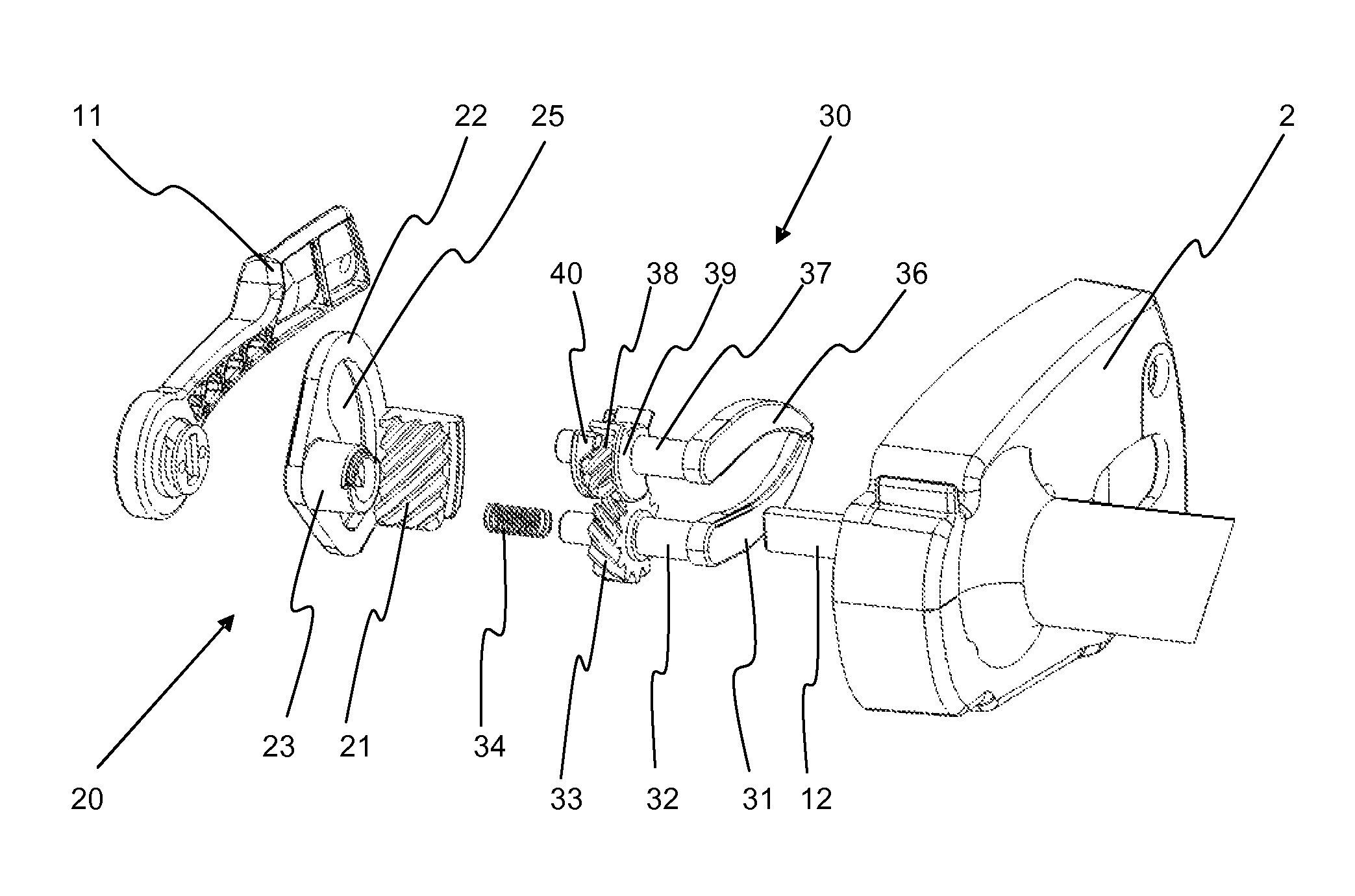
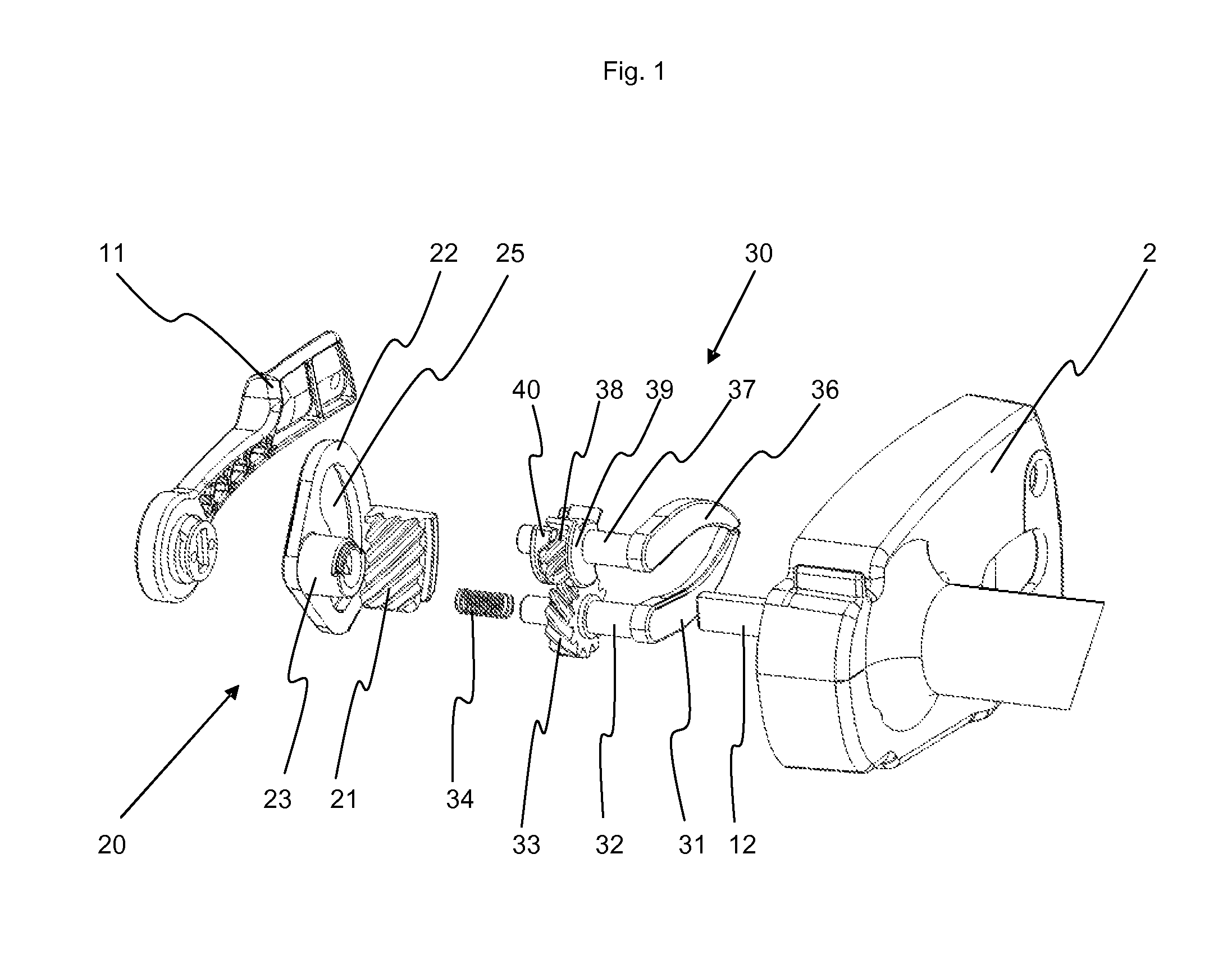
[0032]The holding device (1) according to the invention is constituted essentially by three main elements: a control member (10), a converting and transmitting device (20) and a mechanism for transferring the movement to the arm (30). The whole mechanism, with the exception of the arms, is enclosed in a housing formed by a cover (2) and a bottom (3).

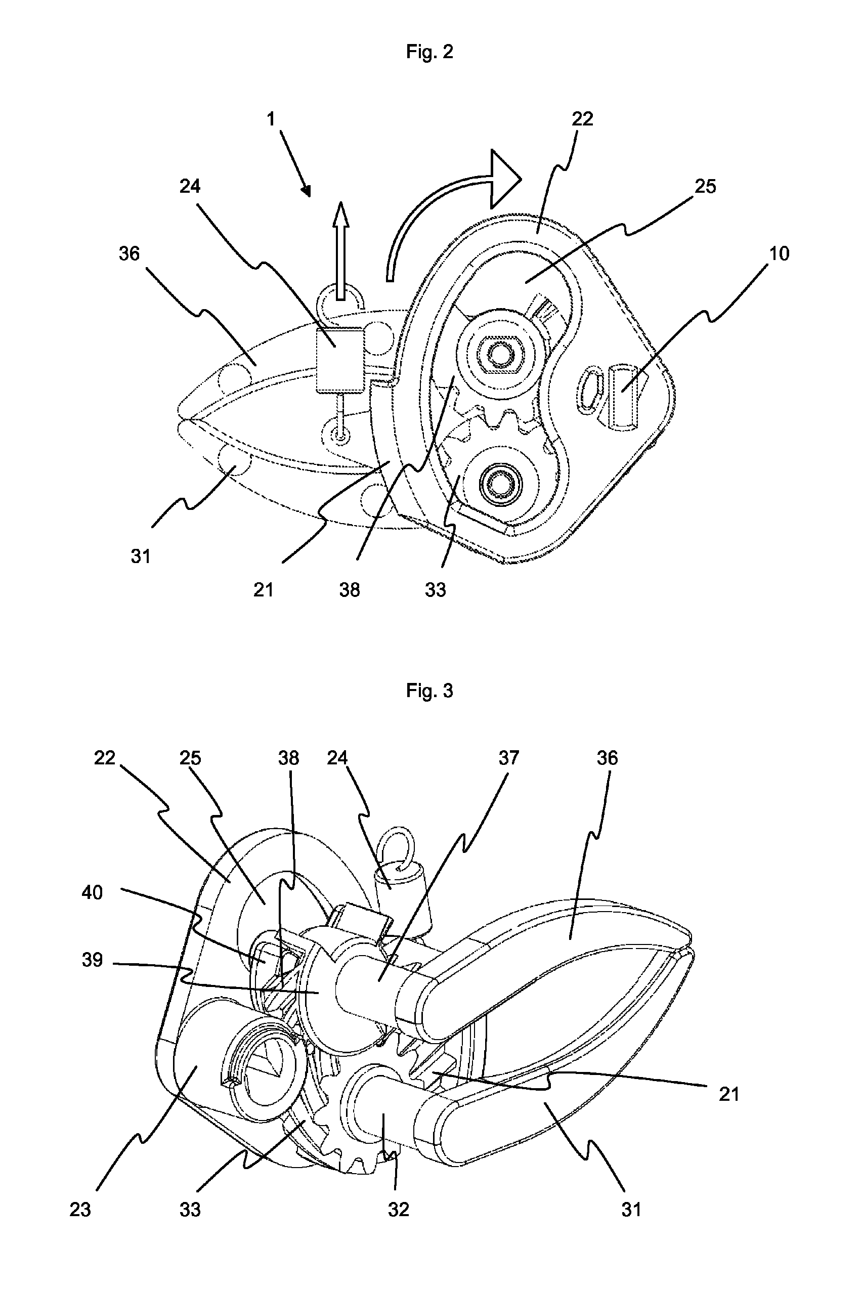
[0033]The arms (31, 36) are placed each on an axis (32, 37) parallel to the axis of the syringe. Each of these arms carries a pinion having a helical set of teeth (33, 38). The sets of teeth of these pinions are preferably slanted at an angle of 45° . The two pinions (33, 38) are designed to cooperate with each other, the slanting direction of their sets of teeth being thus reversed. In order to make the two pinions (33, 38) integral in translation with each other, one of the two, here, the upper pinion (38), is equipped on its two lateral faces with a flange (39, 40). The lateral faces of the teeth of the lower pinion (33) are thus plac...


PUM


Abstract

A holding device for locking the head of a syringe piston on a pusher has arms connected to respective pinions pivotable and translationally displaceable so that the corresponding arm is involved in the same motion between a rest position, in which the arms are closed and pressed against the pusher, and an open position, in which the arms are opened and remote therefrom, the translation is carried out prior to rotation during the movement toward the open position or in reverse order toward the rest position. The holding device also has a control member and means for converting a part of the control member movement by transmitting it to at least one pinion as a translation movement, which are translationally locked, and means for converting a part of the control member movement by transmitting it to at least one pinion as a rotation movement.

Description

BACKGROUND ART[0001]The invention relates to a holding device for locking the head of a syringe piston on a syringe pump pusher, the device being equipped with arms integral each with a pinion pivotable about its axis and movable in translation so as to drive the corresponding arm in a same movement between a rest position, in which the arms are “closed” and “pressed” against the pusher, and an open position, in which the arms are “opened” and “removed” from the pusher, the translation being performed before the rotation during the movement toward the open position, or in reverse order toward the rest position, the holding device further comprising a control member and means for converting a portion of the movement of the control member by transmitting it to at least one pinion in the form of a translation movement and means for converting a portion of the movement of the control member by transmitting it to at least one pinion in the form of a rotation movement.[0002]Syringe pumps ...

Claims


Application Information

Patent Timeline
IPC IPC(8): A61M5/315
CPCA61M5/1458A61M5/1456
Inventor ROCHETTE, FRANCOIS
Owner FRESENIUS VIAL
Why Eureka
Try Eureka