Liquid level sensor

a liquid level sensor and liquid level technology, applied in liquid/fluent solid measurement, instruments, machines/engines, etc., can solve the problems of light to bounce or be received across, measurement accuracy, and the addition of a reflective element, and the cost accordingly to provide such configuration

Inactive Publication Date: 2011-12-06
MCMAHON RANDEL P
View PDF8 Cites 20 Cited by
  • Summary
  • Abstract
  • Description
  • Claims
  • Application Information

AI Technical Summary

Benefits of technology

[0022]Therefore, it is an object of the present invention to provide a new and improved liquid level sensor apparatus, system, and method that may be easily and effectively be used to provide reliable and highly accurate measurements and resolution of liquid in a vessel.
[0030]Another object of the present invention is to provide a new and improved liquid level sensor apparatus, system, and method that may provide a safe method for measuring volatile liquids in harsh environments.

Problems solved by technology

All these prior art devices have the disadvantage of requiring the light to bounce or be received across a space wherein the space must have the liquid pass through.
This obviously creates a region that can be blocked by contaminants and impurities in the liquid thereby making the measurements inaccurate when the amount of light returning to the detector is not true to the level of liquid to be measured.
Each of the above identified electrical optical liquid level sensors and others in the field are adequate in certain situations, but may create difficulties due to the nature of the device and the need for two surfaces, areas, and / or sensors for the liquid to pass.
The obvious disadvantage is the required addition of a reflective element and the cost accordingly to provide such configuration as well as the problems associated with using large vessels and the distance of reflections accordingly.
Currently in the prior art, there is no device or system which is sufficiently sensitive, inexpensive, and robust enough for common daily usage and especially in volatile environments or where extremely accurate readings are desired.

Method used


Image

  • Liquid level sensor
  • Liquid level sensor
  • Liquid level sensor

Examples


Embodiment Construction

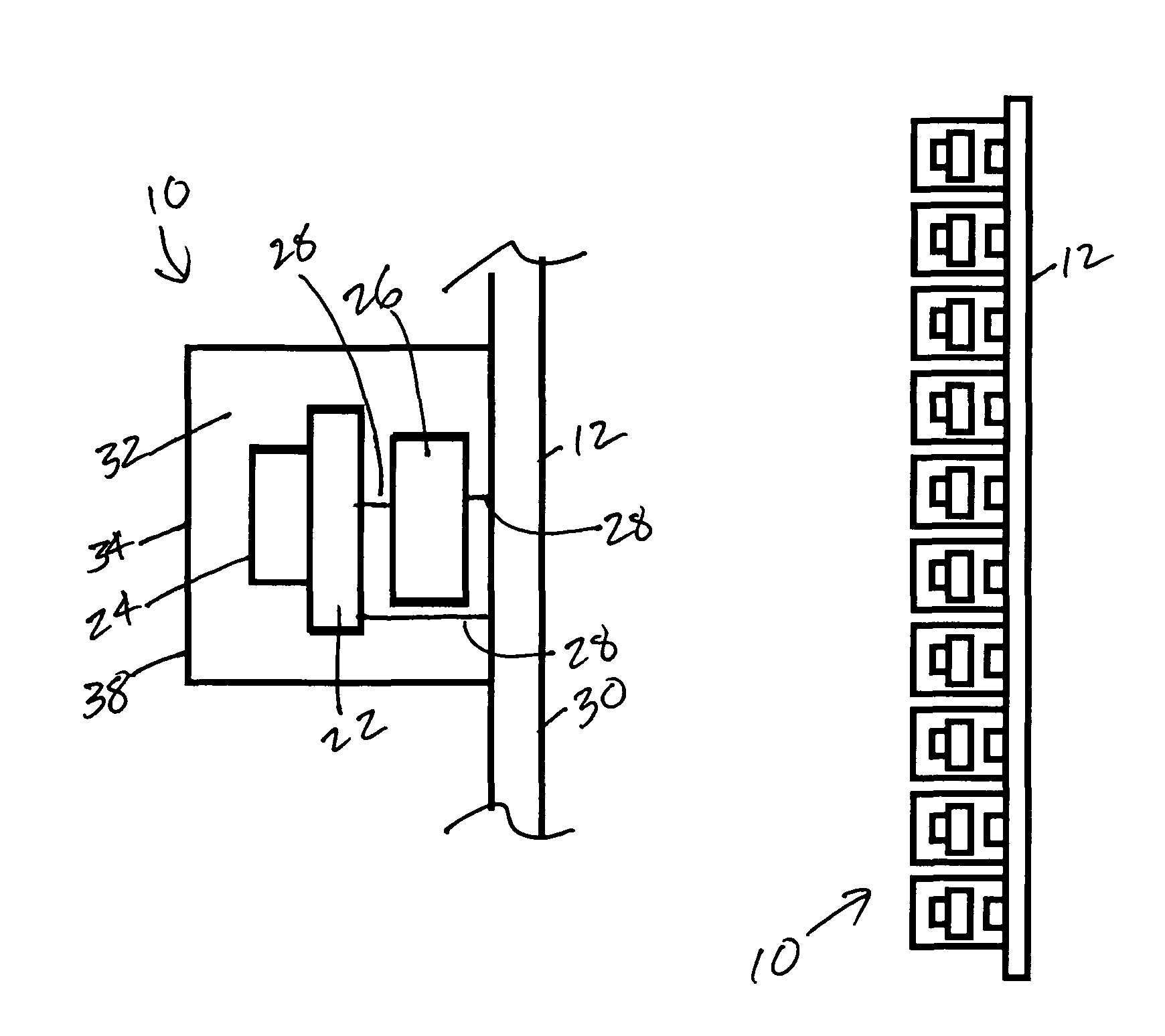
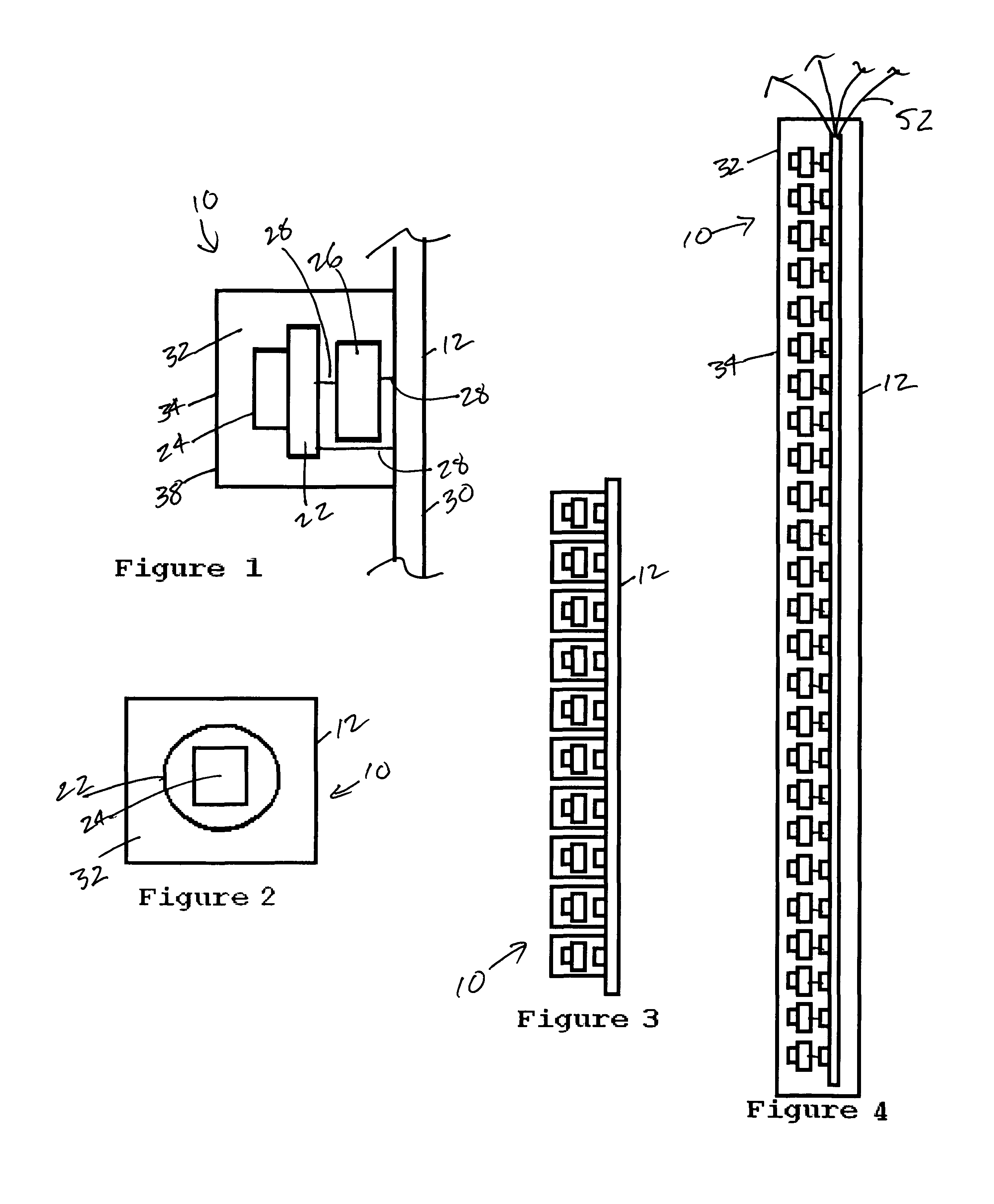
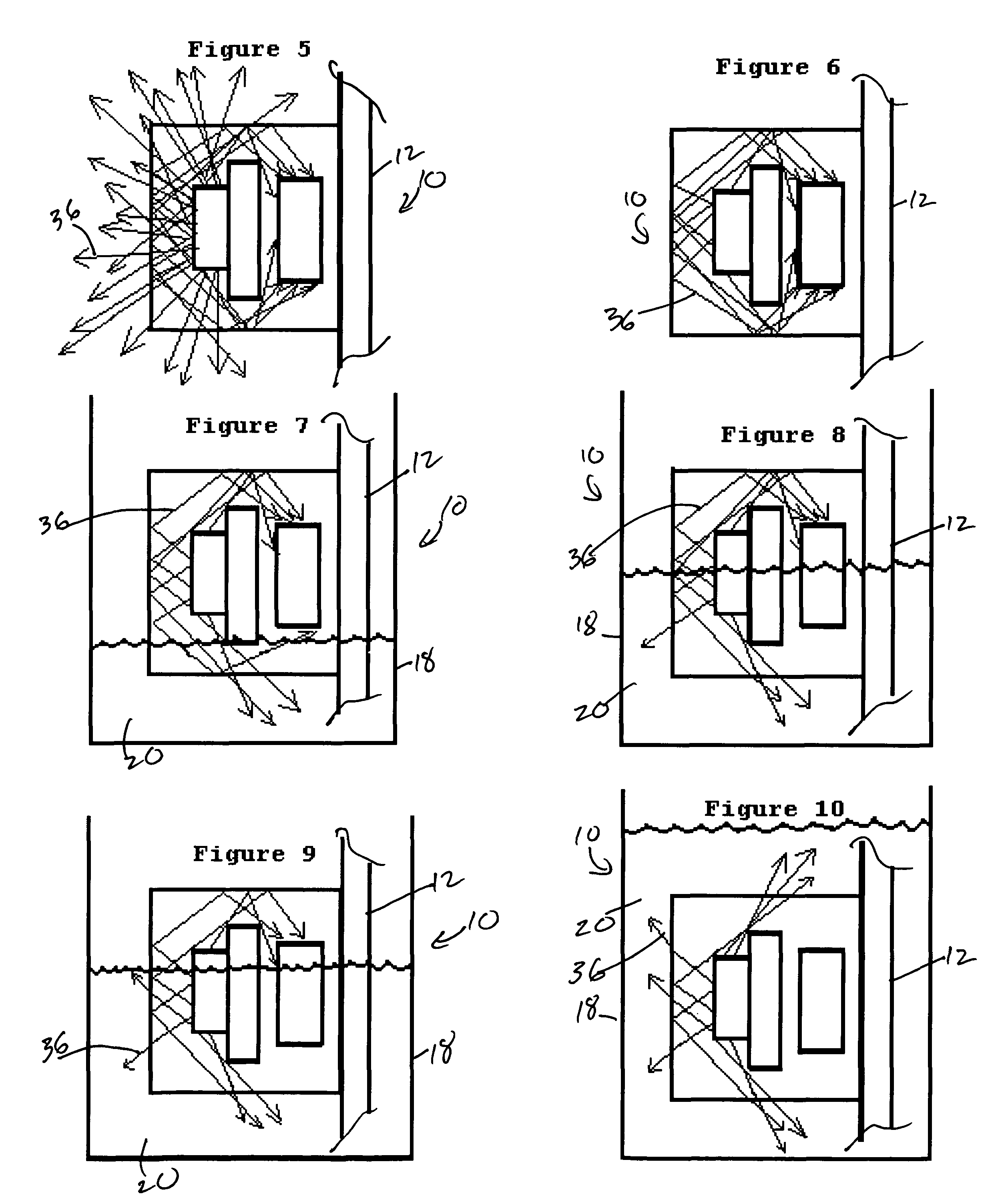
[0041]In a preferred embodiment, the invention 10 generally comprises a fully encapsulated liquid level sensor using optical properties for highly accurate monitoring the liquid level in a vessel apparatus, system, and method. In a preferred construction, invention 10 may include a sensor unit or probe 12, a receiver unit, display, or gauge 14 either analog or digital, and a power source 16 for use with a vessel 18 that may contain liquid 20

[0042]Referring to the illustrations and FIG. 1 in particular, it is contemplated that probe 12 may include an opaque light shield or shield 22 positioned between a light emitting element or emitter 24 and a light sensing element, photosensor or light sensor 26. Electrical connectors 28 may connect the aforementioned to an interconnection substrate or substrate 30. It is contemplated that substrate 30 may be a printed circuit board or other electrical connection method. Electrical connectors 28 are further discussed below along with interconnecti...


PUM

PropertyMeasurementUnit
liquid levelaaaaaaaaaa
lengthaaaaaaaaaa
radiant energyaaaaaaaaaa

Abstract

A liquid level sensor probe for determining liquid level within a vessel, the liquid level sensor probe comprising at least one light source positioned for emitting radiant energy; at least one photosensor positioned for detecting an amount of radiant energy received from at least one light source wherein a change in the amount of radiant energy as detected by at least one photosensor is indicative of a change in liquid level within the vessel; at least one light shield positioned between at least one light source and at least one photosensor wherein at least one light shield prevents radiant energy from directly hitting at least one photosensor; and encapsulation material.

Description

CROSS-REFERENCE TO RELATED APPLICATIONS[0001]Priority is claimed from provisional patent application U.S. Ser. No. 61 / 070,999 filed on Mar. 27, 2008 and incorporated by reference herein.BACKGROUND OF THE INVENTION[0002]1. Field of the Invention[0003]In general, the present invention is an apparatus, system, and method for sensing liquid level in a vessel. More in particular, the present invention generally provides a fully encapsulated liquid level sensor using optical properties for highly accurate monitoring the liquid level in a vessel.[0004]2. Description of the Prior Art[0005]Electrical optical sensing devices are well known in the field of liquid level sensors. They generally employ reflective and refractive optical theory based on the different indices of refraction between two media. Typically, these devices require the liquid to pass between two surfaces wherein the light change is measured as the liquid passes between two locations or through a space.[0006]One such sensor ...

Claims


Application Information

Patent Timeline
Patent Type & Authority Patents(United States)
IPC IPC(8): G01N1/10G01N21/49G01F23/00
CPCG01F23/2927
Inventor MCMAHON, RANDEL P.
Owner MCMAHON RANDEL P
Why Eureka
Try Eureka