Method and apparatus for improving the strength of a utility pole

a technology for utility poles and support poles, applied in the field of support poles, can solve the problems of reducing the operational life of the pole, stress concentration, etc., and achieve the effect of improving the strength of the support pol

Inactive Publication Date: 2011-12-13
EATON INTELLIGENT POWER LTD
View PDF7 Cites 13 Cited by
  • Summary
  • Abstract
  • Description
  • Claims
  • Application Information

AI Technical Summary

Benefits of technology

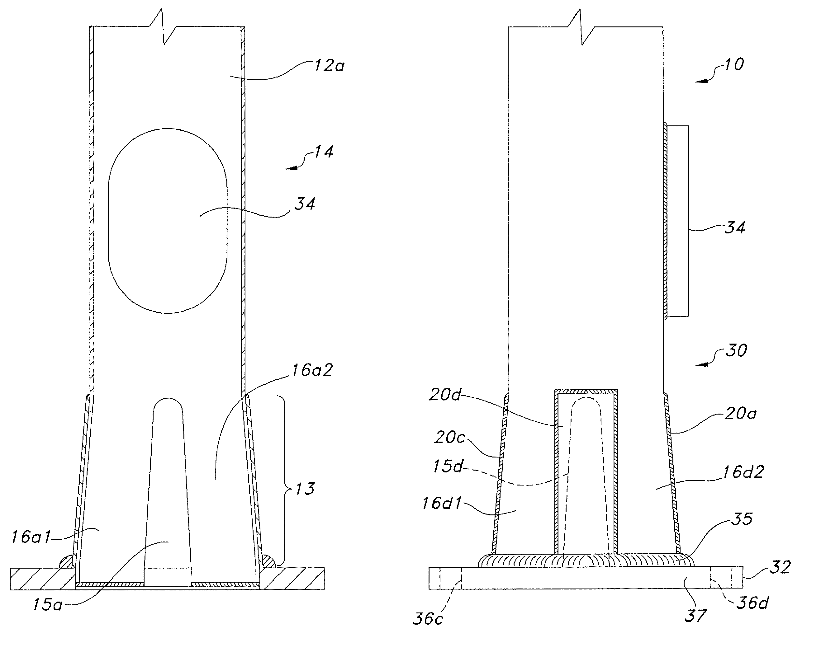
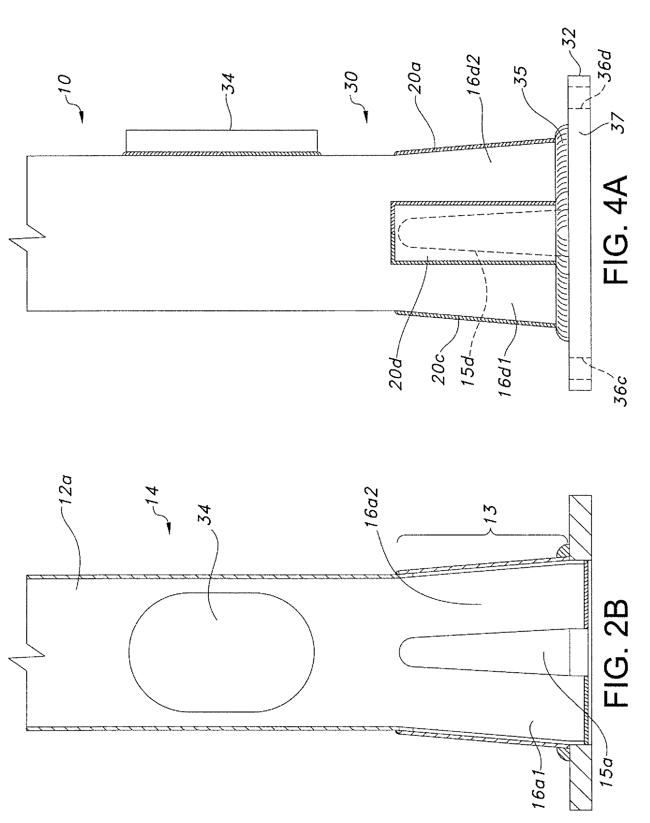
[0005]The present invention relates generally to a support pole redesign that helps reduce stress concentrations and increases the operational life of the support pole. This is facilitated by a greater surface area in contact with the mounting plate due to expansion of the lower end of the support pole, which results in spreading more load to the foundation as described below.
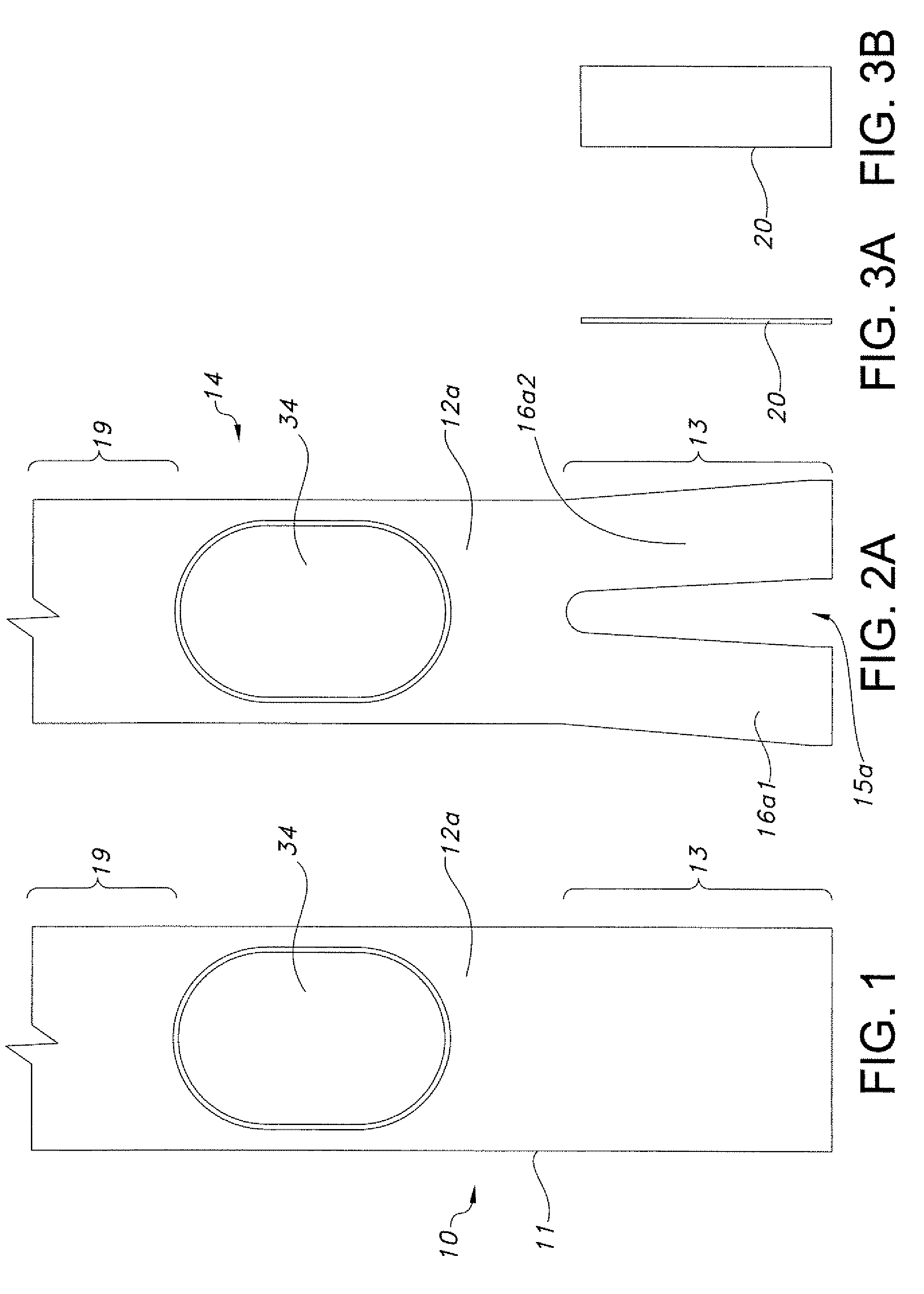
[0008]For yet another aspect of the present invention, a method for improving the strength of the support pole can include the step of providing a support pole that includes an upper end, a lower end, and a plurality of side walls disposed between the two ends. A slit can be cut into each side wall. The slit can be a predetermined length and can extend from the lower end of the support pole toward the upper end. An expansion device can be placed inside the support pole near the lower end and can angularly displace the side walls outward. Reinforcing members can be coupled to each side wall. The reinforcing members can typically cover the slit made in its respective side wall and extend from the bottom of the pole member to a point adjacent to where angular displacement of the side wall is initiated. The lower end of the pole member can then be coupled to a mounting plate.

Problems solved by technology

A problem with conventional support poles involves stress concentrations that occur near the interface between the support pole and the mounting plate.
These stresses decrease the operational life of the pole.

Method used


Image

  • Method and apparatus for improving the strength of a utility pole
  • Method and apparatus for improving the strength of a utility pole
  • Method and apparatus for improving the strength of a utility pole

Examples


Embodiment Construction

[0023]The present invention provides a reinforced support pole with increased strength along its base. The reinforced support pole is created by modifying a basic support pole and coupling reinforcing members in such a manner that the strength of the reinforced support pole along the base is increased. Exemplary embodiments of the present invention can be more readily understood by reference to the accompanying figures.

[0024]It should be understood at the outset that although exemplary embodiments of the invention are illustrated below, the present invention may be practiced using any number of techniques, whether currently known or in existence. The present invention should in no way be limited to the exemplary implementations, drawings, and techniques illustrated below, including the exemplary design and implementation illustrated and described herein.

[0025]Any spatial references herein such as, for example, “top,”“bottom,”“upper,”“lower,”“above,”“below,”“rear,”“between,”“vertical...


PUM


Abstract

A support pole with enhanced strength along it's base includes an elongated pole member secured to a mounting plate. A majority of the length of the pole member has a uniform cross-section. Slits are cut into each side of the pole member along its lower end. A mandrel is placed into the lower end of the pole and expanded, thereby expanding the lower end of the pole away from the center and creating a larger cross-sectional area at its lower end. The lower end of the pole is secured to the mounting plate. Reinforcing members are welded over the expanded slits and the bottom of the reinforcing member is further welded to the mounting plate. The lower section with a larger cross-sectional area increases the moment of inertia and surface area of the support pole, thereby increasing the strength of the support pole.

Description

FIELD OF THE INVENTION[0001]The present application relates generally to support poles used for utility applications. Specifically, the present invention relates to support poles modified by expanding the base of the pole to increase the strength of the pole.BACKGROUND OF THE INVENTION[0002]Support poles are common structures used for a variety of functions, including supporting lamps, holding power lines, antennas, and mounting devices that require a raised vantage point. Support poles are often made with a uniform cross sectional area to a standardized set of dimensions in order to utilize other standardized components. Maintaining adherence to industry standards is necessary in order that replacement poles fit preexisting installations. Typically, a support pole includes an elongated pole which is secured to a mounting plate that anchored in position. Common methods for securing support poles include welding the support pole to the mounting plate.[0003]A problem with conventional...

Claims


Application Information

Patent Timeline
Patent Type & Authority Patents(United States)
IPC IPC(8): F16M13/00
CPCE04H12/2292E04H12/2261
Inventor KUMAR, PRAMODNAGESH, SARESH
Owner EATON INTELLIGENT POWER LTD
Why Eureka
Try Eureka