Unlock instant, AI-driven research and patent intelligence for your innovation.

Enhanced proximity sensing

Inactive Publication Date: 2011-12-13
MONTEREY RES LLC
View PDF10 Cites 27 Cited by
  • Summary
  • Abstract
  • Description
  • Claims
  • Application Information

AI Technical Summary

Benefits of technology

[0007]Accordingly, embodiments of the present invention are directed to a method for rejecting sensor information when a mechanical switch is being pressed in a user interface device having sensors over switches. A mechanical switch in the process of being pressed may be determined based on an increase in pressure which may be determined by measuring the increase in capacitance at a plurality of capacitive sensors over a multitude of sample times. The rejection of sensor information when it is determined that the switch is being pressed allows the user interface to more accurately and smoothly report a user's commands.
[0008]More specifically, an embodiment of the present invention is directed to a method for detecting a switch being pressed, the method includes measuring an increase in a capacitance of a plurality of adjacent capacitive sensors, measuring a change in the quantity of a plurality of sensors changing in capacitance, determining whether a button is being pressed and rejecting data from said plurality of adjacent capacitive sensors to reduce the detection of false input.
[0009]Another embodiment of the present invention is directed to a method for determining whether a button is being pressed and includes measuring changes in the proximity of an object with a plurality of sensors, determining whether the pressure of an object is increasing, wherein the pressure of an object is determined based on the magnitude of change in proximity of said plurality of sensors. To reduce the detection of false inputs, the method also includes not transmitting information related to the proximity of said object.
[0010]Another embodiment of the present invention is a system including a plurality of sensors, a plurality of switches, wherein the switches are adjacent to the plurality of sensors, and a control unit for communicating with an apparatus and coupled to the plurality of sensors and the plurality of switches, wherein the control unit determines a change in pressure based on signals from the plurality of sensors and based on the change in pressure ignores information from the plurality of sensors. The control unit determines the change in pressure to accurately determine whether a user is pressing one of the plurality of switches or using the capacitive sensors to interact with a device.

Problems solved by technology

This premature reporting of activity often leads to jittery and unintentional performance of functions associated with the sensors (e.g., position) and thus is undesirable.
For example, if switch 120 corresponded to a play button and the capacitive sensors corresponded to volume control, a user trying to push play may unintentionally change the volume.
This non-response period means that a user may be trying enter commands but the system will not register them and thus the user interface will not be smooth and responsive leading to an undesired experience.

Method used


Image

  • Enhanced proximity sensing
  • Enhanced proximity sensing
  • Enhanced proximity sensing

Examples


example operations

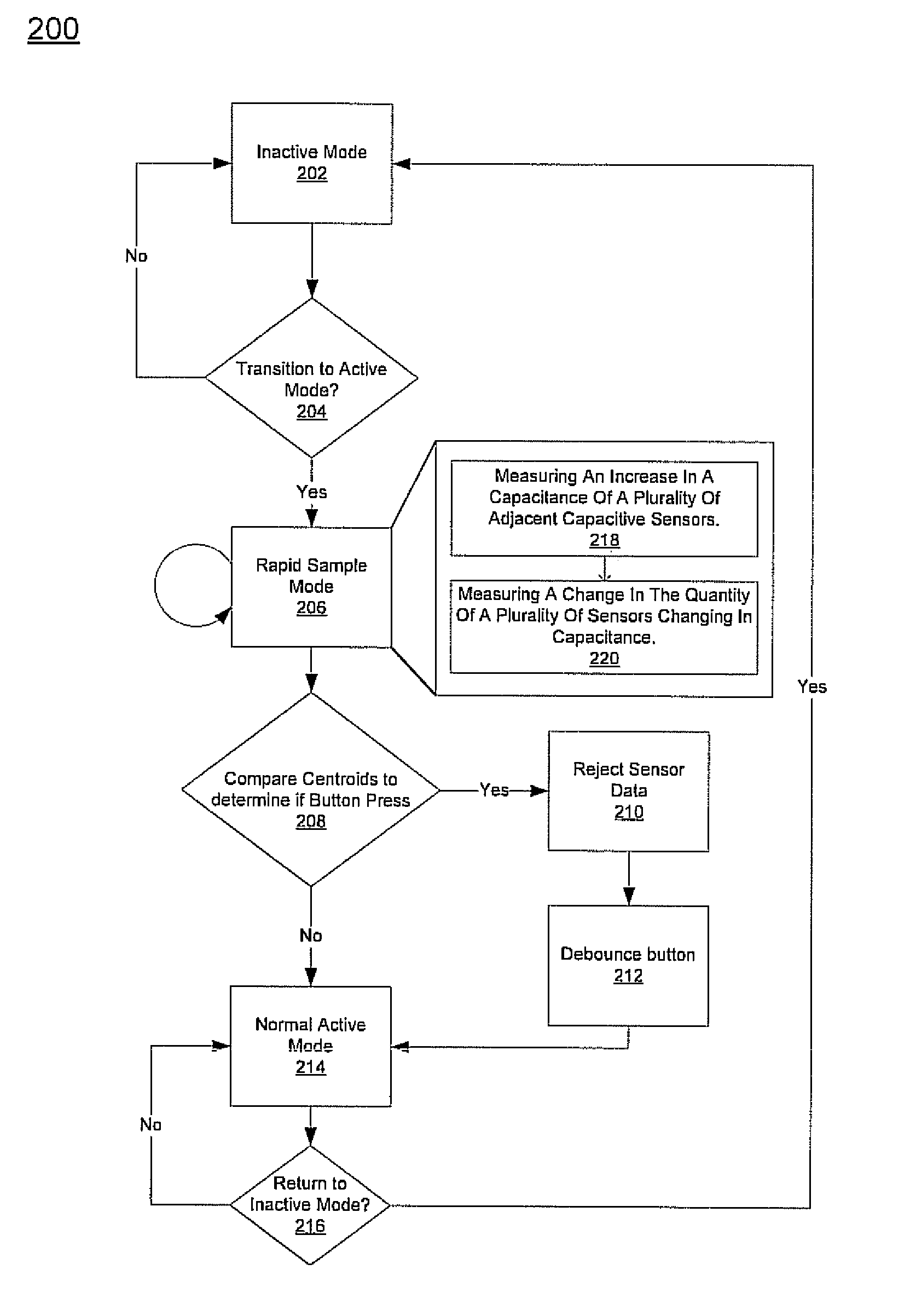
[0017]With reference to FIGS. 2-3, flowcharts 200 and 300 each illustrate example functions used by various embodiments of the present invention. Flowcharts 200 and 300 include processes that, in various embodiments, are carried out by a processor under the control of computer-readable and computer-executable instructions. Although specific function blocks (“blocks”) are disclosed in flowcharts 200 and 300, such steps are examples. That is, embodiments are well suited to performing various other blocks or variations of the blocks recited in flowcharts 200 and 300. It is appreciated that the blocks in flowcharts 200 and 300 may be performed in an order different than presented, and that not all of the blocks in flowcharts 200 and 300 may be performed.

[0018]FIG. 2 is a flowchart 200 of an exemplary process for detecting the pressing of a switch or button in accordance with an embodiment. The blocks of flowchart 200 may be carried out on a plurality of devices such as those used for na...


PUM


Abstract

An embodiment of the present invention is directed to a method for rejecting sensor information when a switch is being pressed in a system having sensors over switches. A switch in the process of being pressed may be determined based on an increase in pressure which may be determined by measuring the increase in capacitance at a plurality of capacitive sensors. The rejection of sensor information when the switch is being pressed allows the user interface to more accurately thus facilitates smooth and jitterless interface operation.

Description

RELATED U.S. APPLICATIONS[0001]This application claims the benefit of and priority to the copending provisional patent application Ser. No. 60 / 921,160, entitled “Enhanced Proximity Sensing,” with filing date Mar. 30, 2007, and hereby incorporated by reference in its entirety.FIELD OF INVENTION[0002]Embodiments of the present invention relate to the sensors above switches.BACKGROUND OF THE INVENTION[0003]Conventional menu navigation devices and interface devices (e.g. a touch pad) use sensors which are placed above switches or buttons to determine centroids and allow a user to indicate position or invoke functions associated with the switches. Capacitive sensors may be used to determine a position of an object, such as a finger. For example, a touch pad may use capacitive sensors to allow a user to move a cursor around and use switches to invoke right and left click functions.[0004]FIGS. 1A-1C show a conventional design for a capacitive sensor and switch based device. Specifically, F...

Claims


Application Information

Patent Timeline
IPC IPC(8): G01R27/26G06F3/041
CPCG06F3/044H03K17/9622H03K2217/960705
Inventor BEST, ANDREWBIRCH, ROBERTBOKMA, LOUISPETERSON, JONATHAN R.
Owner MONTEREY RES LLC