Semi-extensible steel soil reinforcements for mechanically stabilized embankments

a steel soil reinforcement and mechanical stabilization technology, applied in mining structures, excavations, artificial islands, etc., can solve the problems of inability to accommodate the stresses placed on the rods inside the earthen embankment, the expansion of the reinforcement is completely impossible, and the system is prone to system failure. , to achieve the effect of stabilizing the earthen structure and reducing the strain on the elongated soil reinforcement elements

Active Publication Date: 2011-12-20
HILFIKER WILLIAM K +2
View PDF32 Cites 26 Cited by
  • Summary
  • Abstract
  • Description
  • Claims
  • Application Information

AI Technical Summary

Benefits of technology

[0018]A further objective is to provide a mechanically stabilized embankment system that allows sufficient movement within an earthen structure so that it may move to the “active” condition, thereby stabilizing the earthen structure and reducing the strain on the elongate soil reinforcement elements.

Problems solved by technology

The disadvantage of such systems is that the reinforcements are completely extensible, and there is nothing to limit the stretching of the reinforcements.
Over-stretching the reinforcements weakens them and may cause movement of the face and failure of the system.
While the steel rods of this second category function to deform under the stresses adjacent the wall, they are not able to accommodate stresses placed upon the rods inside the earthen embankment.
Since the rods are not extensible within the earthen embankment, they must be made with sufficiently steel to prevent failure within the earthen embankment, this driving up the costs of the system
However, this form of “swiggle” anchor is unable to accommodate movement within the earthen structure.
The prior art provides extensible plastic reinforcements, and non-extensible steel rods that include deformable, bent portions at either the proximal or distal ends; however, the prior art does not teach semi-extensible elongate soil reinforcement elements that include bent sections through the middle of the elongate soil reinforcement elements, that are partially extensible.

Method used


Image

  • Semi-extensible steel soil reinforcements for mechanically stabilized embankments
  • Semi-extensible steel soil reinforcements for mechanically stabilized embankments
  • Semi-extensible steel soil reinforcements for mechanically stabilized embankments

Examples


first embodiment

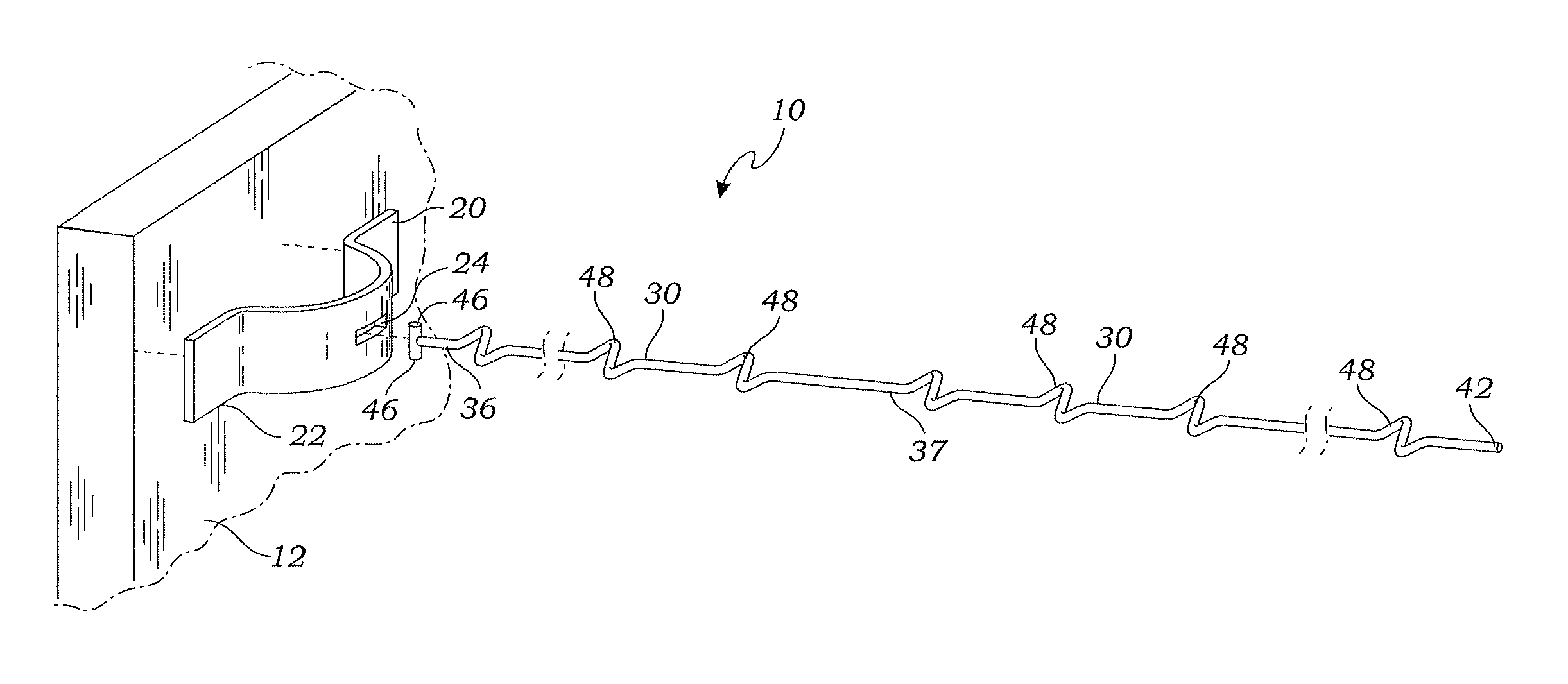
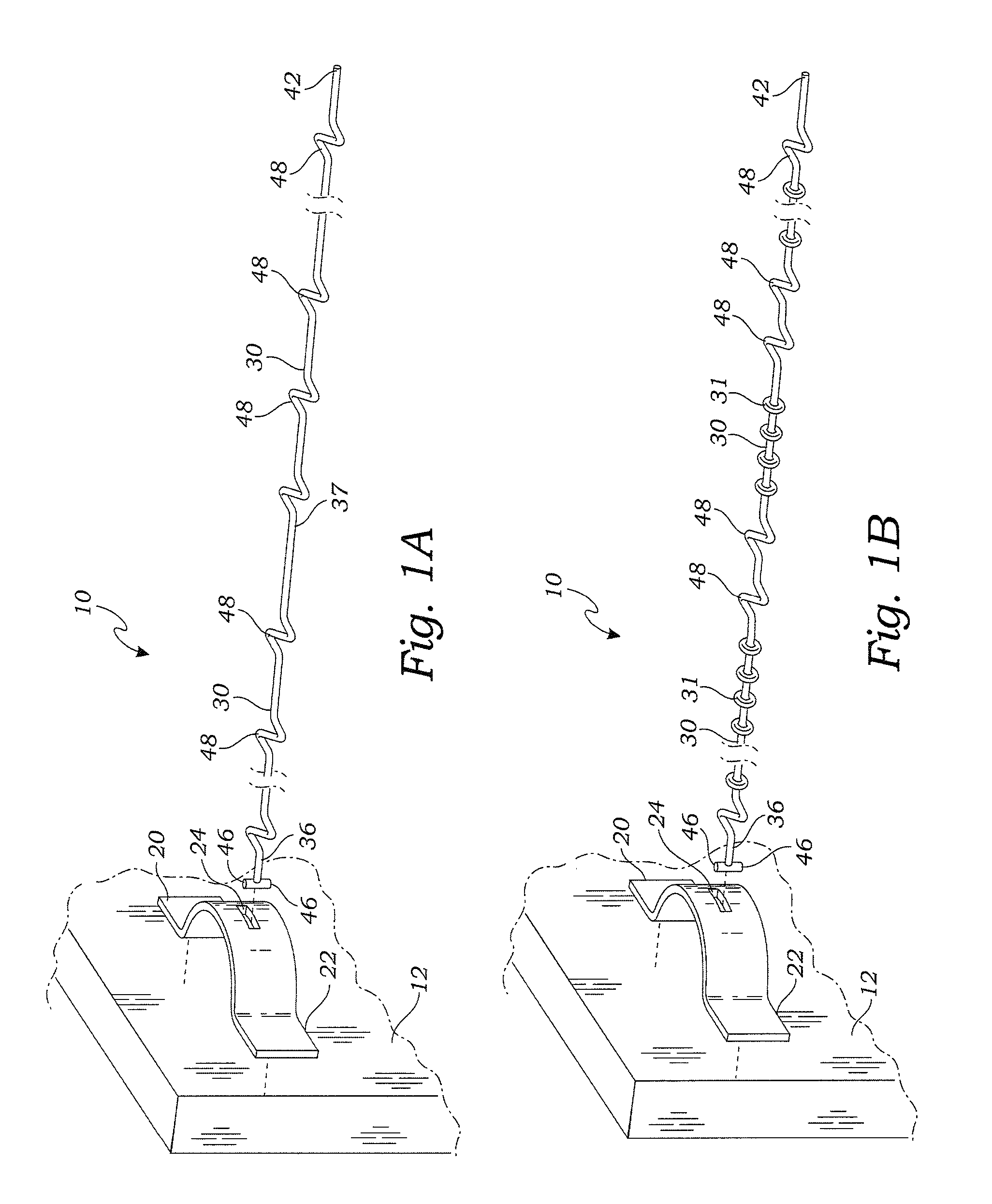
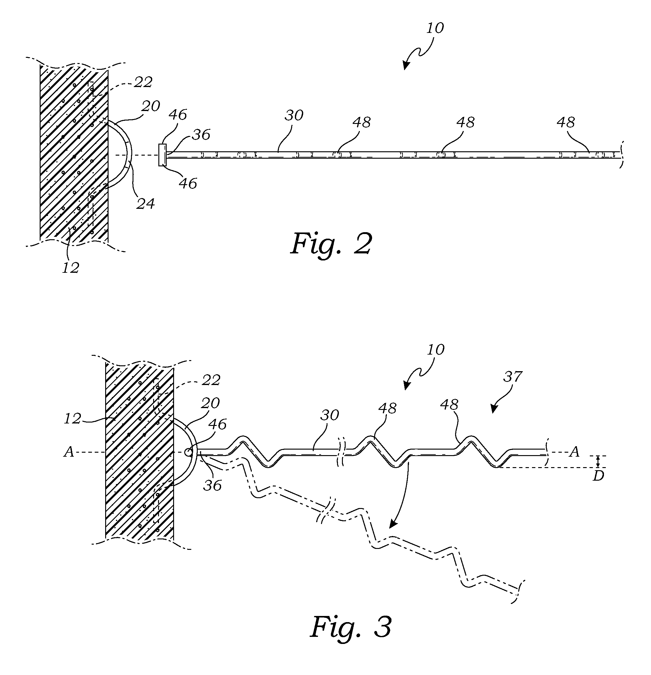
[0041]FIGS. 1A and 1B are exploded perspective views of the mechanically stabilized embankment system 10, illustrating a rod form of the elongate soil reinforcement element 30, with FIG. 1B including ribs 31 described in greater detail below. FIG. 2 is a top plan view thereof, illustrating the elongate soil reinforcement element 30 once it has been rotated 90° for insertion into a connection element 20. FIG. 3 is a top plan view thereof once the elongate soil reinforcement element 30 has been inserted into the connection element 20 and rotated back ninety degrees to a locked position.

[0042]As illustrated in FIGS. 1A-3, in a first embodiment the connection element 20 is a connection bracket. In this embodiment, the connection bracket 20 may include a wall engaging element 22 and a first interlocking element 24. The wall engaging element 22 is adapted for engaging the wall facing element 12. In the embodiment of FIGS. 1-3, the connection bracket 20 has a generally U-shaped cross-secti...

third embodiment

[0057]FIG. 8 is a perspective view of the mechanically stabilized embankment system 60. As illustrated in FIG. 8, in this embodiment the connection bracket is provided by an engagement portion 62 of a wire mesh 64 that provides the wall facing element in this embodiment. The soil reinforcement elements 30 may be attached to each other with a plurality of lateral elements 66 (e.g., rods or other connectors), forming a horizontal mat structure that is adapted to be installed in the earthen embankment.

[0058]FIG. 9 is a top plan view of an alternative embodiment of the means for connecting the soil resistance elements 30 to the wall facing element, in this case a wire mesh 80 similar to the wire mesh 64 illustrated in FIG. 8. In this embodiment, the wire mesh 80 includes vertical supports 82 that are positioned in close proximity to each other, and these vertical supports 82 provide the connection element. The second interlocking element, in this embodiment, is provided by a C-shaped an...


PUM


Abstract

A mechanically stabilized embankment system has a connection element adapted for engaging a wall facing element. An elongate soil reinforcement element is adapted to be attached to the connection element and positioned in earthen embankment. A plurality of semi-extensible bent segments are integrally formed by and spaced on a middle portion of the elongate soil reinforcement element such that each semi-extensible bent segment extends laterally from an axis of the elongate soil reinforcement element, but can be pulled straight upon the application of excessive force that might otherwise break the elongate soil reinforcement element.

Description

CROSS-REFERENCE TO RELATED APPLICATIONS[0001]This application for a utility patent claims the benefit of U.S. Provisional Application No. 61 / 054,012, filed May 16, 2008.STATEMENT REGARDING FEDERALLY SPONSORED RESEARCH[0002]Not ApplicableBACKGROUND OF THE INVENTION[0003]1. Field of the Invention[0004]This invention relates generally to mechanically stabilized embankment systems, and more particularly to a mechanically stabilized embankment system that includes a wall facing element connected to elongate soil reinforcement elements each having a plurality of semi-extensible bent segments spaced along the length of the soil reinforcement element.[0005]2. Description of Related Art[0006]The prior art teaches various forms of mechanically stabilized embankment systems for stabilizing earthen embankments. These systems include a wall facing element connected to elongate soil reinforcement elements that extend into the earthen embankment. The prior art elongate soil reinforcement elements ...

Claims


Application Information

Patent Timeline
Patent Type & Authority Patents(United States)
IPC IPC(8): E02D29/02
CPCE02D29/0233
Inventor HILFIKER, WILLIAM K.HILFIKER, WILLIAM B.HILFIKER, HAROLD K.
Owner HILFIKER WILLIAM K
Why Eureka
Try Eureka