
Hinge and an electronic device with the same

a technology of electronic devices and hinges, applied in the field of hinges, can solve the problems of high cost of conventional hinges and difficulty in adjusting friction, and achieve the effect of reducing manufacturing costs and less precise size of other components

Inactive Publication Date: 2011-12-27
SHIN ZU SHING
View PDF14 Cites 10 Cited by
  • Summary
  • Abstract
  • Description
  • Claims
  • Application Information

AI Technical Summary

Benefits of technology

The adjustable friction mechanism allows for customizable holding force at various angles while preventing the second pivoting assembly from departing, enhancing user experience and reducing manufacturing costs.

Problems solved by technology

Therefore, the resilient arms and the sleeve should be precisely made to provide adequate friction so that the conventional hinge is cost high and is not easy to adjust the friction.

Method used


Image

  • Hinge and an electronic device with the same
  • Hinge and an electronic device with the same
  • Hinge and an electronic device with the same

Examples


Embodiment Construction

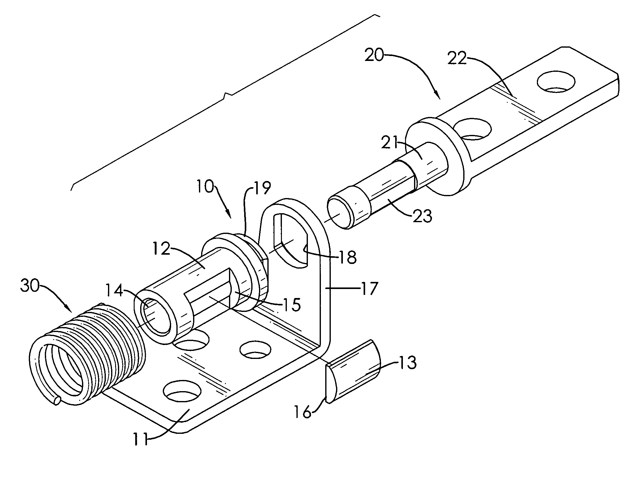
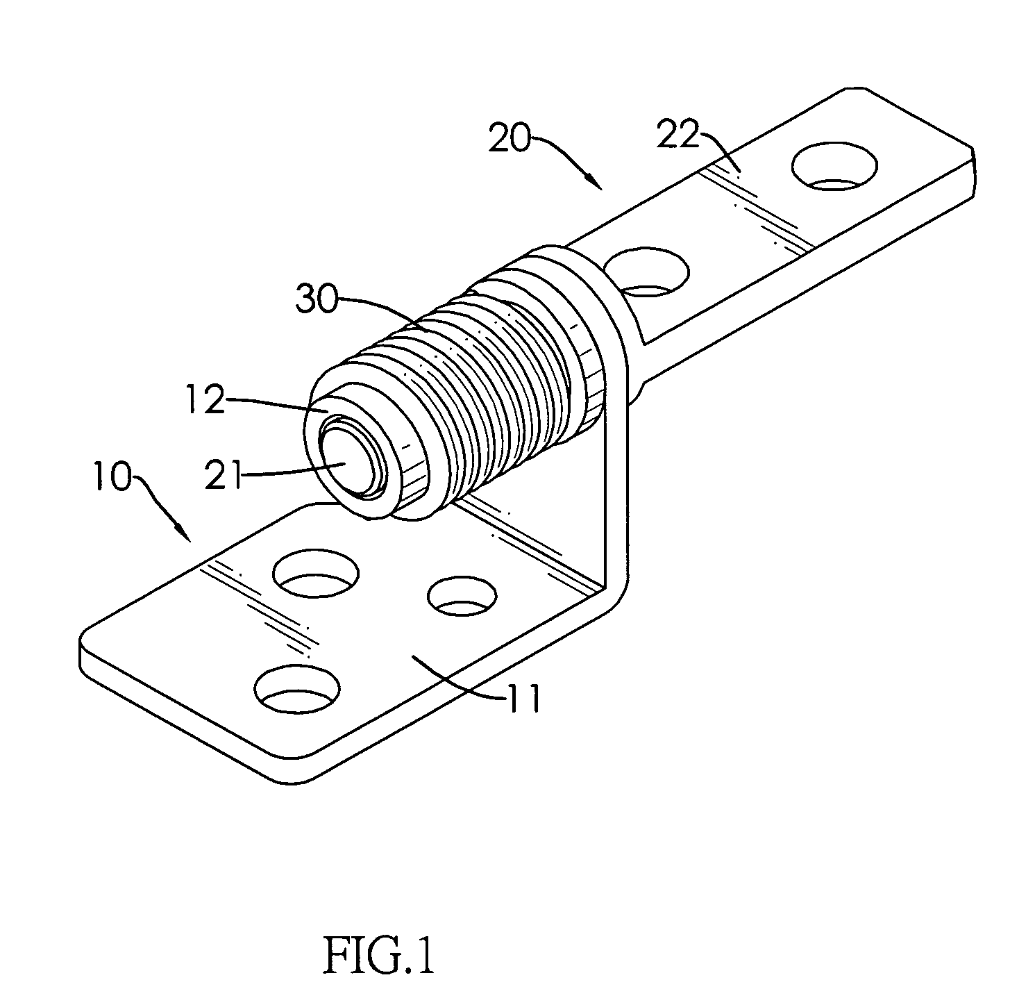
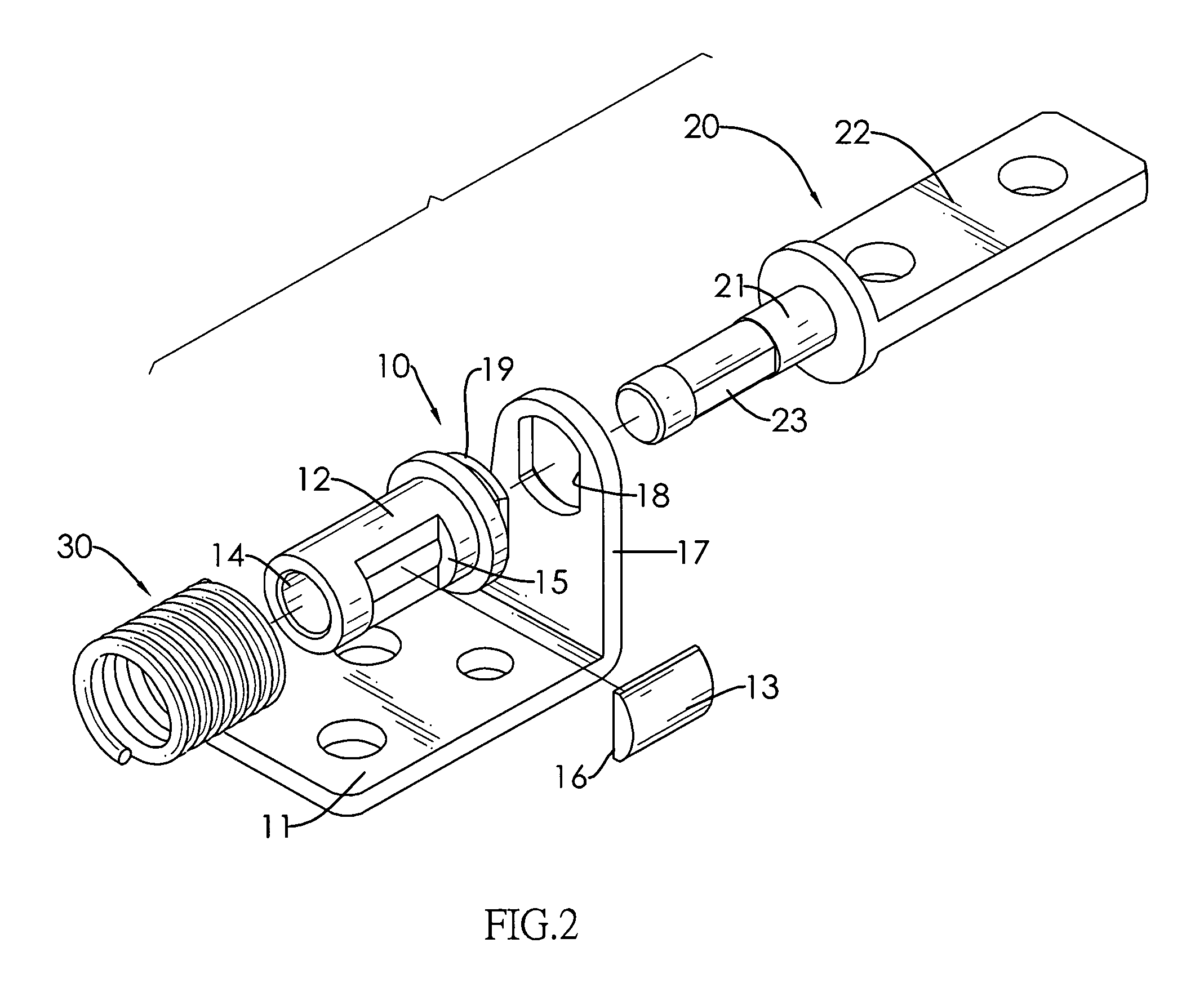
[0029]With reference to FIGS. 1 to 3, a hinge in accordance with the present invention comprises a first pivoting assembly (10), a second pivoting assembly (20) and a resilient unit (30).

[0030]The first pivoting assembly (10) comprises a connecting bracket (11), a sleeve (12) and a resilient plug (13). The sleeve (12) is connected to the connecting bracket (11) and has a longitudinal cavity (14) and a mounting recess (15). The longitudinal cavity (14) may be formed through the sleeve (12). The mounting recess (15) is formed in a sidewall of the sleeve (12) and communicates with the longitudinal cavity (14). The resilient plug (13) is mounted tightly in the mounting recess (15) and has a positioning surface (16) exposed to the longitudinal cavity (14).

[0031]The second pivoting assembly (20) is connected to the sleeve (12) and has a pintle (21) and a mounting bracket (22). The pintle (21) is mounted in the longitudinal cavity (14) of the sleeve (12) and has a positioning section (23)....


PUM


Abstract

A hinge is mounted in an electronic device with a cover and a base. The hinge has a first pivoting assembly, a second pivoting assembly and a resilient unit. The first pivoting assembly has a resilient plug. The resilient plug is mounted between the second pivoting assembly and the resilient unit to provide friction and to keep the second pivoting assembly from departing from the first pivoting assembly. The friction is adjusted by changing the resilience of the resilient plug or the resilient unit, or by changing the thickness of the resilient plug. Therefore, preciseness of the size of other component is less required to reduce the manufacturing cost.

Description

BACKGROUND OF THE INVENTION[0001]1. Field of the Invention[0002]The present invention relates to a hinge, especially to a hinge for an electronic device having adjustable friction and anti-departing function.[0003]2. Description of the Prior Arts[0004]Hinges are mounted between a cover and a base of an electronic device to provide pivoting. When the cover is pivoted, the hinge provides friction to hold the cover at any desired visual angle.[0005]A conventional hinge comprises a first segment and a second segment. The first segment has a sleeve and is connected to the cover of the electronic device. The second segment has a pair of resilient arms and is connected to the base of the electronic device. The resilient arms are inserted into the sleeve, urge and rub against the sleeve. When the cover is pivoted, the sleeve is rotated relative to the resilient arms to provide friction.[0006]However, the friction is determined by the size of the resilient arms. Therefore, the resilient arms...

Claims


Application Information

Patent Timeline
Patent Type & Authority Patents(United States)
IPC IPC(8): E05D11/08
CPCH04M1/0216Y10T16/533Y10T16/54035Y10T16/54038
Inventor CHIEN, HSIANG-CHI
Owner SHIN ZU SHING
Learn More