Ripper autodig system implementing machine acceleration control

a technology of autodigging and acceleration control, applied in the field of autodigging system, can solve the problems of machine slip, higher resistance, and slip representing the error between driven speed and actual machine travel speed

Active Publication Date: 2011-12-27
CATERPILLAR INC
View PDF88 Cites 32 Cited by
  • Summary
  • Abstract
  • Description
  • Claims
  • Application Information

AI Technical Summary

Problems solved by technology

The ground surface can include non-homogenous loose soil or compacted material that can be easy or difficult for the machine to process.
As the machines traverse a site that has changing terrain and / or varying ground surface conditions, the magnitude of resistance applied to the implements by the material also varies, and higher amounts of resistance can lead to machine slip.
Generally, slip represents the error between driven speed and actual machine travel speed.
This continuous altering can be tiring for even a skilled operator and difficult, if not impossible, for a novice operator to achieve optimally.
Although the control system of the '539 patent may improve machine efficiency and reduce operator fatigue by automating some of the functions normally controlled by the operator, it may be limited.
That is, because the control system only considers load, as measured at the shank, there may be situations when the load on the shank is below the predetermined load and, yet, the shank penetration is too deep for maximum productivity such as when the machine is on a loose or viscous surface and slipping.
In addition, because the control system only controls shank operation, the operator may still be required to expend time and energy controlling machine functions such as speed and acceleration.

Method used


Image

  • Ripper autodig system implementing machine acceleration control
  • Ripper autodig system implementing machine acceleration control
  • Ripper autodig system implementing machine acceleration control

Examples


Embodiment Construction

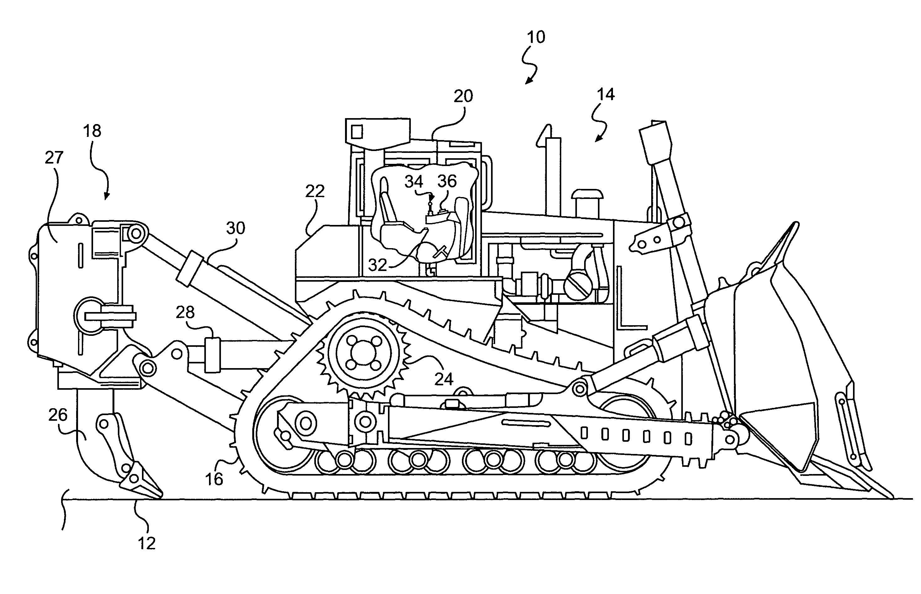
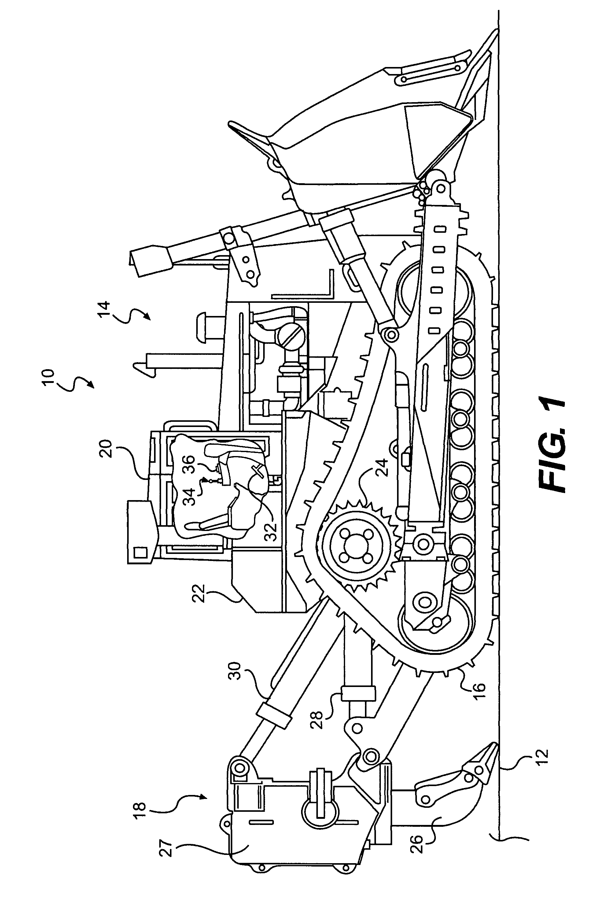
[0011]FIG. 1 illustrates an exemplary machine 10. Machine 10 may include any mobile machine that performs some type of operation associated with an industry, such as, for example, mining, construction, farming, or any other industry known in the art. For example, machine 10 may be an earth moving machine such as a dozer, a loader, a backhoe, an excavator, a motor grader, or any other earth moving machine. Machine 10 may traverse a work site to manipulate material beneath a work surface 12, e.g. transport, cultivate, dig, rip, and / or perform any other operation known in the art. Machine 10 may include a power source 14 configured to produce mechanical power, a traction device 16, at least one ripper 18, and an operator station 20 to house operator controls. It is contemplated that machine 10 may additionally include a frame 22 configured to support one or more components of machine 10.

[0012]Power source 14 may be any type of internal combustion engine such as, for example, a diesel e...


PUM


Abstract

A control system for a machine having a power source, a traction device, and a ripping tool is disclosed. The control system may have a slip sensor configured to generate at least one signal indicative of machine slippage, and at least one actuator operable to position the ripping tool. The control system may also have a controller in communication with the slip sensor, the at least one actuator, and the power source. The controller may be configured to receive at least one operator input indicative of an acceptable slip value, and determine actual machine slippage based on the at least one signal. The controller may also be configured to directly and separately regulate a speed of the machine and a position of the ripping tool during an excavation process based on the acceptable slip value and actual machine slippage.

Description

TECHNICAL FIELD[0001]The present disclosure relates to an autodig system and, more particularly, to a ripper autodig system that implements machine acceleration control.BACKGROUND[0002]Mobile excavation machines, such as, for example, dozers, agricultural tractors, and scrapers, often include one or more material engaging implements utilized to cultivate, dig, rip or otherwise disturb a ground surface. The ground surface can include non-homogenous loose soil or compacted material that can be easy or difficult for the machine to process. As the machines traverse a site that has changing terrain and / or varying ground surface conditions, the magnitude of resistance applied to the implements by the material also varies, and higher amounts of resistance can lead to machine slip. Generally, slip represents the error between driven speed and actual machine travel speed. In order to ensure that a maximum productivity of the machine is attained without damaging the machine (i.e. a maximum am...

Claims


Application Information

Patent Timeline
Patent Type & Authority Patents(United States)
IPC IPC(8): A01B63/112
CPCE02F3/84E02F9/2029E02F5/32
Inventor KNIGHT, JR., ROBERT PAUL
Owner CATERPILLAR INC
Why Eureka
Try Eureka