Motor
a motor and motor technology, applied in the field of motors, can solve the problems of inability to obtain uniform flux content and inability to achieve desired characteristics thereby, and achieve the effects of reducing the amount of material used, uniform flux, and superior characteristics
- Summary
- Abstract
- Description
- Claims
- Application Information
AI Technical Summary
Benefits of technology
Problems solved by technology
Method used
Image

Examples
first embodiment
[0047]the present invention will now be discussed with reference to FIGS. 1A to 3.
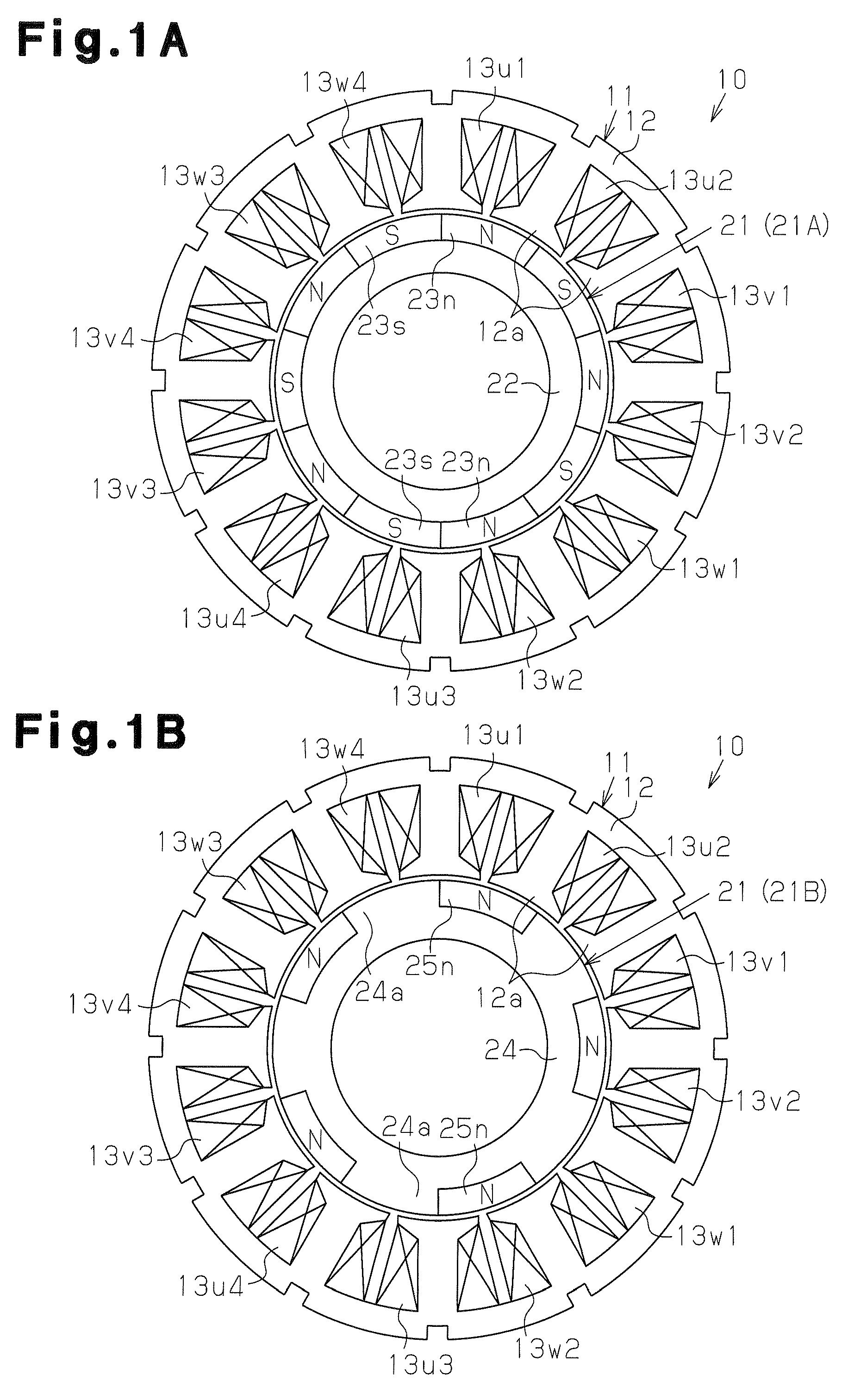
[0048]A brushless motor 10 of the present embodiment is of an inner rotor type including an annular stator 11 and a rotor 21, which is rotatably arranged at an inner side of the stator 11.
[0049]The stator 11 includes an annular stator core 12 having twelve teeth 12, which have identical shapes, extend radially inward, and are arranged at equal angular intervals in the circumferential direction. The stator core 12 is a stacked core formed by a plurality of magnetic metal plates stacked in an axial direction. A coil is wound into a concentrated winding around each tooth 12a of the stator core 12. In the stator 11, coils 13u1 to 13u4, 13v1 to 13v4, 13w1 to 13w4 for the three phases of U, V, and W phases are respectively wound around predetermined sections to form “twelve” magnetic pole portions.
[0050]In the present embodiment, the number of coils for each phase is four, and a total of 12 coils are wound i...
fifth embodiment
[0112]A fifth embodiment according to the present invention will now be discussed with reference to FIGS. 24A to 26 centering on differences from the third embodiment.
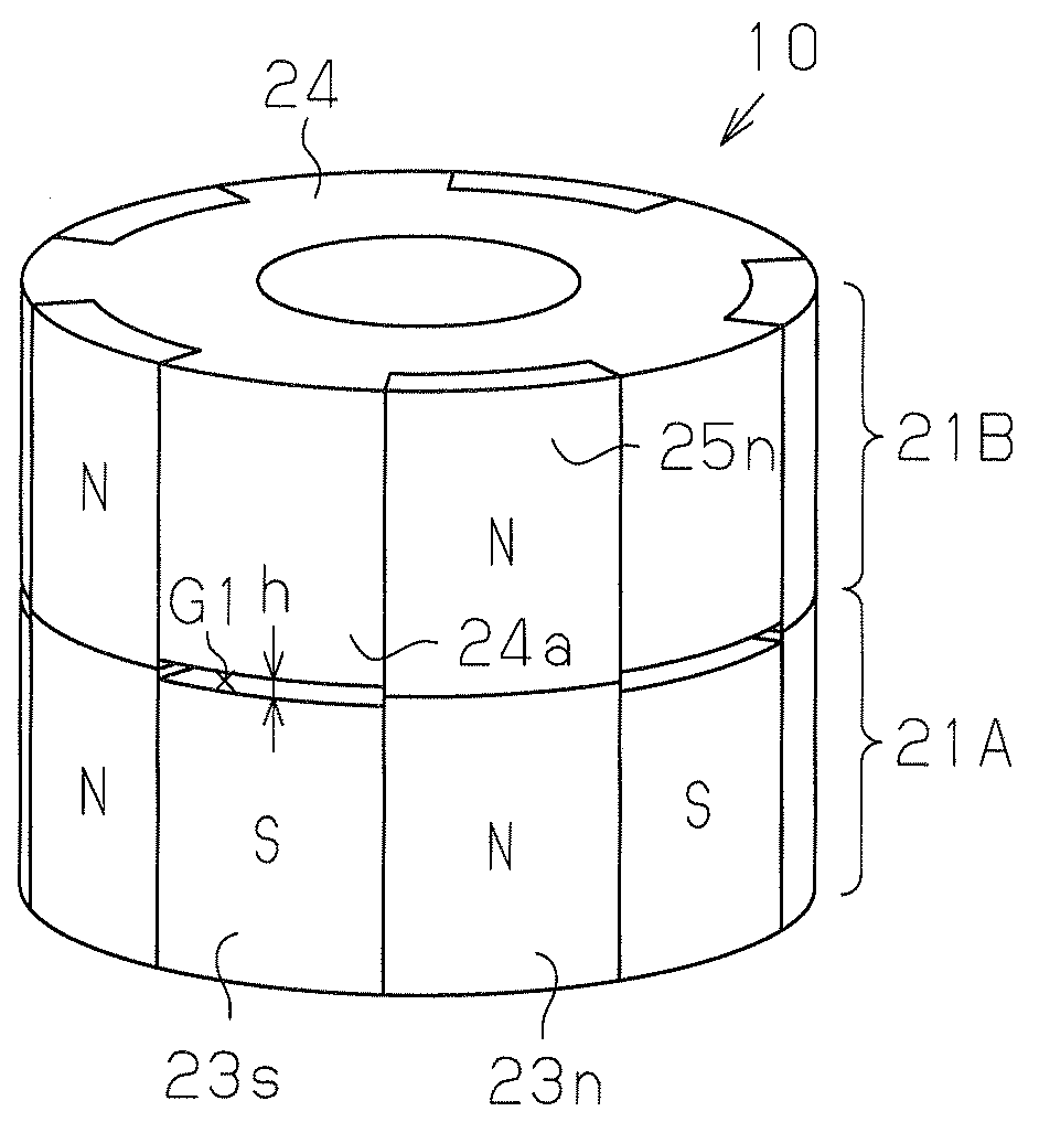
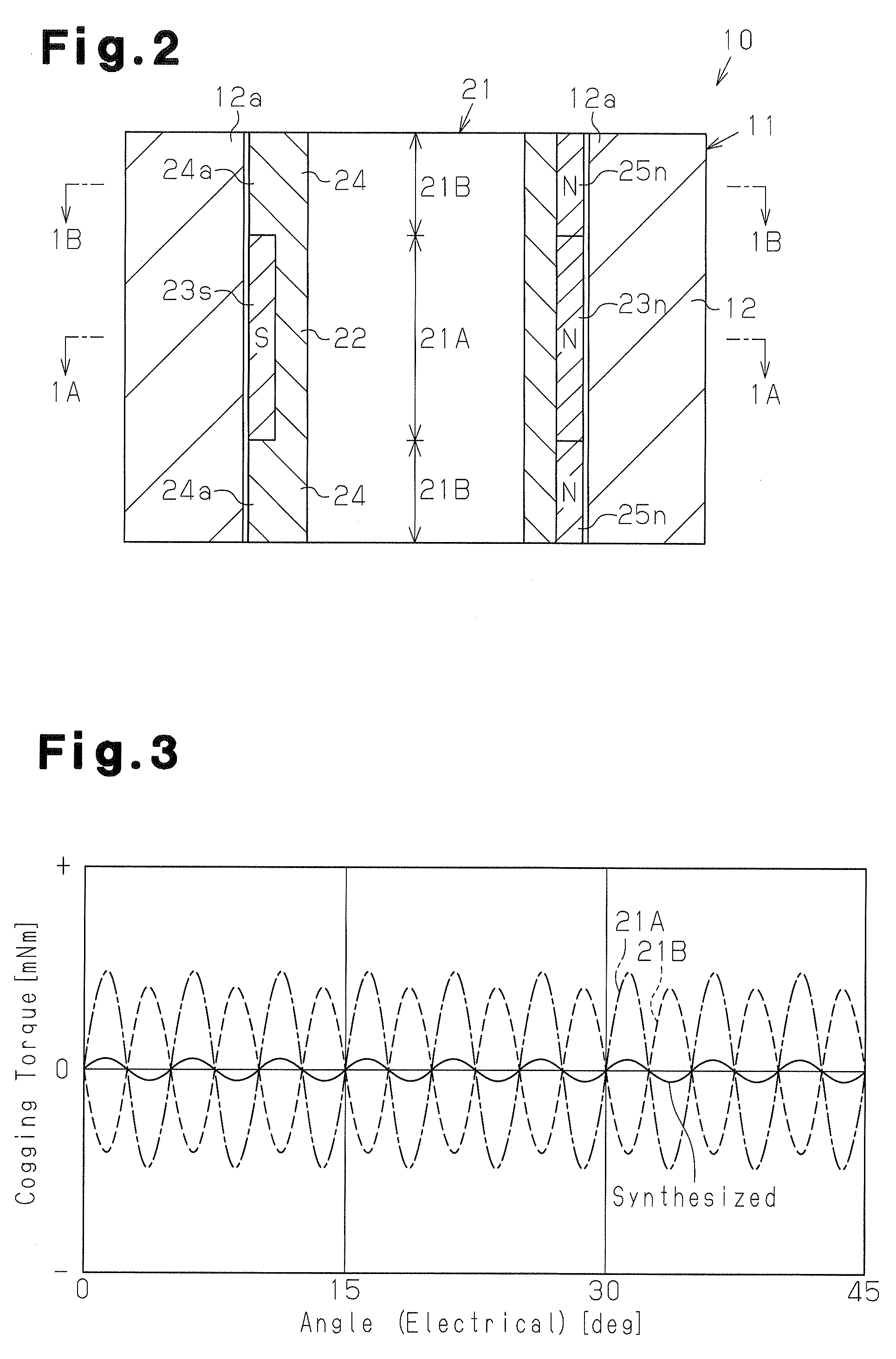
[0113]In the rotor 21 of the present embodiment, the N-pole magnets (first magnets) 23n and the N-pole magnets (third magnets) 25n are arranged to be continuous in the axial direction. A void G1 (short-circuit magnetic flux prevention gap) serving as a magnetic spacer is formed between the S-pole magnets (second magnets) 23s and the salient poles 24a. The void G1 may be filled with resin. The void G1 has a uniform axial distance h along the circumferential direction of the magnet 23. A void G0 (air gap) is formed between the rotor 21 and the stator 11. The void G0 has a uniform radial distance g along the circumferential direction of the rotor 21. A predetermined ratio is set between the distance h of the void G1 and the distance g of the void G0.
[0114]FIG. 26 shows an effective flux content ratio and a leakage flux co...
seventh embodiment
[0137]A seventh embodiment according to the present invention will now be discussed with reference to FIGS. 28A to 28C centering on differences from the sixth embodiment.
[0138]The first units 21A of the rotor 21 in the present embodiment have an IPM structure (Interior Permanent Magnet structure) instead of the normal structure (SPM structure).
[0139]The first rotor core 22 of the first unit 21A includes three receptacles 22n, which are linear, orthogonal to the radial direction, and arranged at equal angular intervals of 120°. The N-pole magnets 23n, which are shaped as rectangular plates, are inserted into and fixed to the receptacles 22b. The portions of the first rotor core 22 located radially outward from the receptacles 22b define magnet side magnetic pole portions 22c that function as N-poles in cooperation with the magnets 23n. The magnet side magnetic pole portions 22c are arranged at an equal angular interval of 120° and are each formed over an angular range of about 60°.
[0...
PUM
 Abstract
Description
Claims
Application Information
 - R&D
- Intellectual Property
- Life Sciences
- Materials
- Tech Scout
- Unparalleled Data Quality
- Higher Quality Content
- 60% Fewer Hallucinations
Browse by: Latest US Patents, China's latest patents, Technical Efficacy Thesaurus, Application Domain, Technology Topic, Popular Technical Reports.
© 2025 PatSnap. All rights reserved.Legal|Privacy policy|Modern Slavery Act Transparency Statement|Sitemap|About US| Contact US: help@patsnap.com