
Scissor action compression assembly tool

a technology of compression assembly and scissor action, which is applied in the field of compression assembly hand tools, can solve the problems of inconvenient operation of tools for some users, undetected large opening angle of handles, and more difficult to grasp, and achieve the effect of convenient operation

Inactive Publication Date: 2012-01-03
RIPLEY TOOLS
View PDF8 Cites 6 Cited by
  • Summary
  • Abstract
  • Description
  • Claims
  • Application Information

AI Technical Summary

Benefits of technology

[0014]Bearing in mind the problems and deficiencies of the prior art, it is therefore an object of the present invention to provide compression assembly tool that is easily operated and does not need to open to a large handle opening angle.
[0015]It is another object of the present invention to provide a compression assembly tool that operates with low hand force.
[0020]In one aspect of the invention, the front end pivot of the lever handle is mounted to the tool body at a point that is closer to the pair of split base supports than the front end of the plunger. This provides for a very long lever handle which helps achieve good compression and sufficient compression distance travel of the plunger.

Problems solved by technology

Although the increased opening angle reduces the hand force that must be applied, it produces a tool that may be awkward for some users to operate.
However, the mechanical advantage achieved by extending the handle beyond the pivot it drives, i.e., by connecting the driving pivot at a point near the middle of the moving lever, results in an undesirably large handle opening angle.
The longer handles are not only more difficult to grasp, they may create clearance problems when used in limited spaces.
Another problem with large opening angles is that a human hand can apply progressively greater force as the hand closes.

Method used


Image

  • Scissor action compression assembly tool
  • Scissor action compression assembly tool
  • Scissor action compression assembly tool

Examples


Embodiment Construction

)

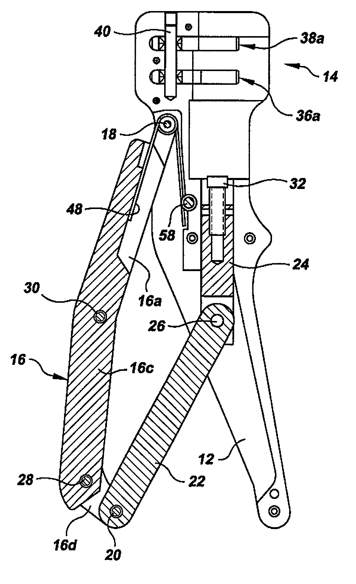
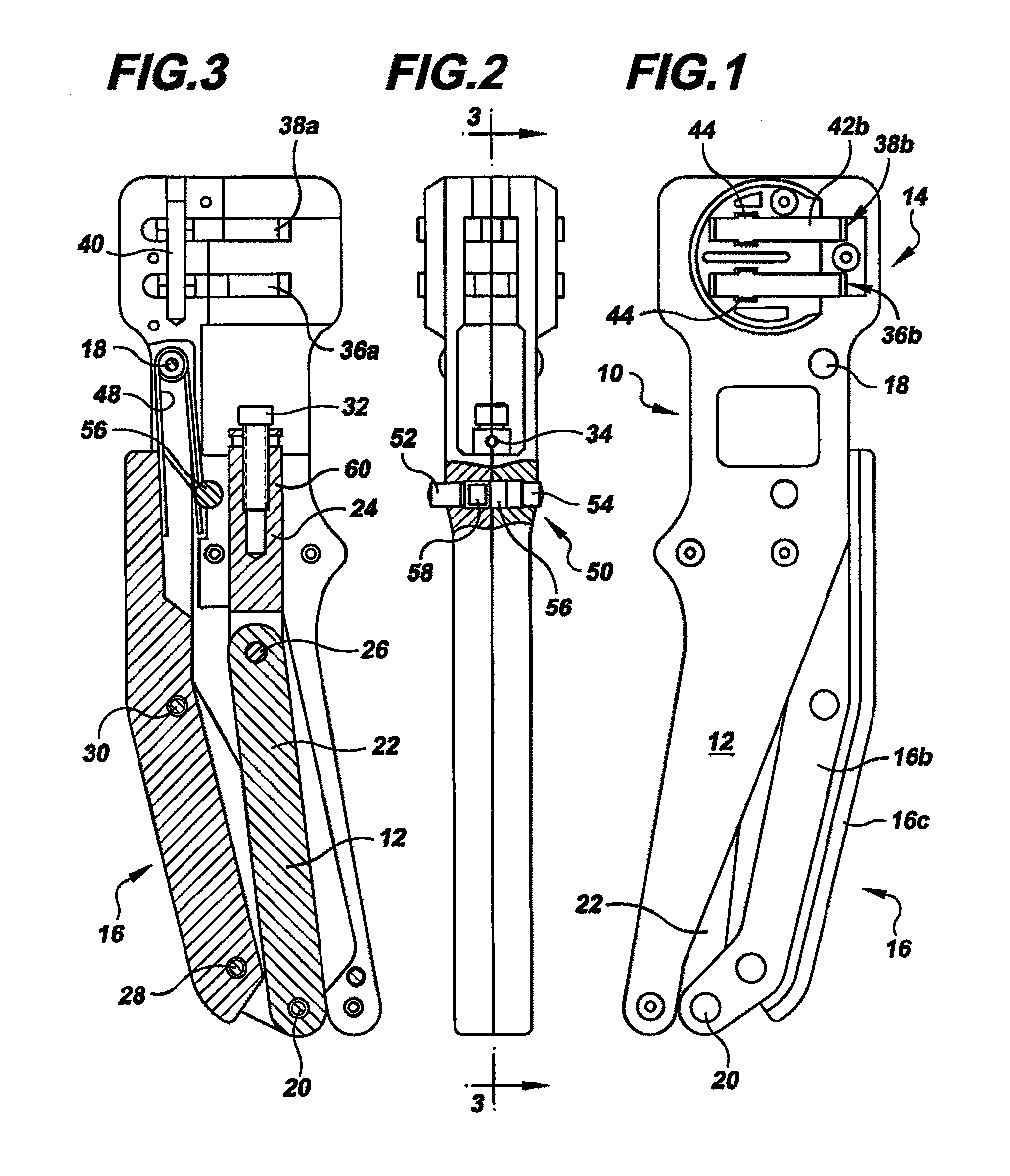
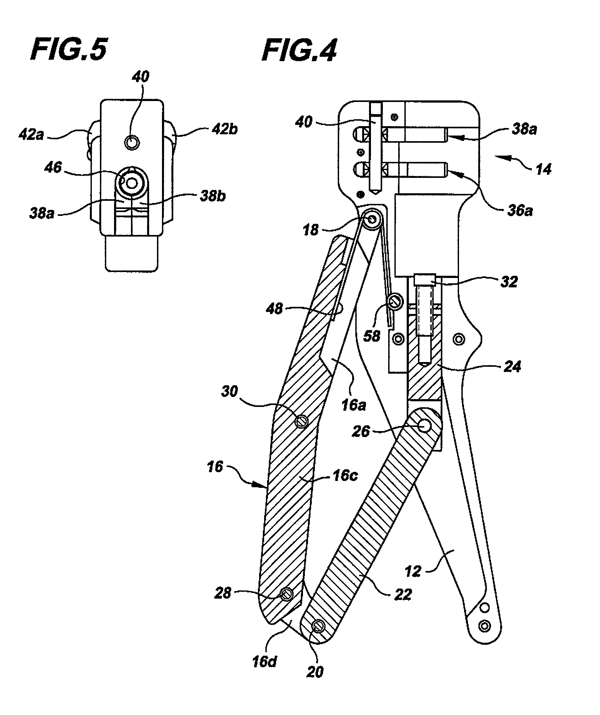
[0037]In describing the preferred embodiment of the present invention, reference will be made herein to FIGS. 1-5 of the drawings in which like numerals refer to like features of the invention.

[0038]Referring to FIGS. 1-5, a preferred embodiment of the compression assembly tool includes a tool body 10 having a fixed handle 12 and a compression head 14. A lever handle 16 includes pivots 18, 20 at the front and back ends of the lever handle. The lever handle 16 is connected to the tool body through the front end pivot 18, which allows the lever handle to rotate relative to the fixed handle and the tool body through an opening angle of approximately 16 degrees. The back end of the lever handle is connected to a link 22 through the back end pivot 20.

[0039]The link 22 is connected to an axially sliding plunger 24 via plunger pivot 26. As may be seen in FIG. 4, as the handle 16 swings about the front end pivot 18, the back end pivot 20 pulls the link 22, which draws the plunger 24 away f...


PUM

PropertyMeasurementUnit
opening angleaaaaaaaaaa
handle opening angleaaaaaaaaaa

Abstract

A compression assembly tool for attaching a connector to a coaxial cable includes a tool body that supports a connector to be compressed in a compression head, a fixed handle, a moving lever handle, and an axially sliding plunger. The lever handle is pivotally connected to the tool body at the front end and to a link at the back end. The connection of the link to the back end of the lever handle and the placement of pivot points at opposite ends of the lever handle provides a scissor action appearance. The relative lengths of the lever handle, plunger and link and the placement of the pivots provides high levels of compression force and sufficient compression travel by the plunger to compress connectors of different lengths while requiring only a very limited handle opening angle, which allows maximum hand strength to be applied to the tool handles.

Description

BACKGROUND OF THE INVENTION[0001]1. Field of the Invention[0002]The present invention relates to compression assembly hand tools for attaching a connector to a coaxial cable by compressing the connector in a direction parallel to the axis of the cable. More specifically, the present invention relates to compression assembly tools that minimize the opening angle of the handles so that they operate in the range where the hand can apply the greatest closing force while still providing a long compression stroke. The invention also relates to compression assembly hand tools, which are preferably capable of compressing connectors of different sizes.[0003]2. Description of Related Art[0004]One known type of compression assembly hand tool is used to attach a connector to a coaxial cable by compressing the connector in a direction parallel to the axis of the cable. A variety of connector designs are available that are attached by compression assembly tools that apply the compression force in...

Claims


Application Information

Patent Timeline
Patent Type & Authority Patents(United States)
IPC IPC(8): H01R43/042
CPCH01R9/05H01R43/0425Y10T29/53226Y10T29/53235Y10T29/53257
Inventor TARPILL, ANDREW J.ZAGULA, TADEUSZ
Owner RIPLEY TOOLS
Learn More