Connector and connector combination for balanced transmission

a technology of balanced transmission and connectors, applied in the direction of coupling contact members, connection contact member materials, coupling device connections, etc., can solve the problems of unbalanced transmission, unbalanced transmission transmitting data, difficult to reduce pitch, etc., to reduce the number of parts, reduce pitch, and high-speed signal transmission

Inactive Publication Date: 2012-01-03
FUJITSU COMPONENENT LTD
View PDF2 Cites 47 Cited by
  • Summary
  • Abstract
  • Description
  • Claims
  • Application Information

AI Technical Summary

Benefits of technology

[0011]Another and more specific object of in one embodiment of the present invention is to provide a connector and a connector combination, which may reduce the number of parts, reduce the pitch at which the contacts are arranged, and achieve a high-speed signal transmission.

Problems solved by technology

When transmitting data among computers, peripheral equipments, circuit boards, and the like, either the unbalanced transmission or the balanced transmission may be employed.
The unbalanced transmission transmits the data by a signal voltage with respect to a ground potential.
In addition, it may be difficult to reduce the pitch at which the ground contacts and the signal contact pairs are alternately arranged.
In other words, it may be difficult to provide a large number of signal contact pairs without increasing the size of the plug connector along the longitudinal direction thereof.
However, in the general plug connector or the proposed plug connector for the balanced transmission, the ground contact is formed by a plurality of parts, and for this reason, it may be difficult to reduce the number of parts forming the plug connector.
In addition, because each signal contact pair of the proposed plug connector is isolated by the second member of the ground contact, it may be difficult to reduce pitch at which the ground contact and the signal contact pairs are alternately arranged.
Furthermore, the proposed plug connector may not be able to cope with the recent demands to perform high-speed signal transmission.
Such a resonance may cause the noise to increase.

Method used


Image

  • Connector and connector combination for balanced transmission
  • Connector and connector combination for balanced transmission
  • Connector and connector combination for balanced transmission

Examples


first embodiment

[0028]A description will be given of the connector in a first embodiment of the present invention.

[0029](Plug Connector)

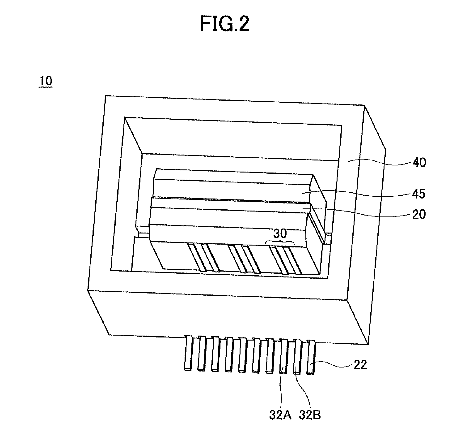
[0030]FIG. 2 is a perspective view illustrating an example of the plug connector in the first embodiment of the present invention. FIG. 3 is a perspective view illustrating conductor parts of the plug connector in the first embodiment, by omitting illustration of insulator parts.

[0031]As illustrated in FIGS. 2 and 3, the plug connector 10 includes a (first) ground contact 20 and a plurality of (first) signal contact pairs 30. The ground contact 20 and the plurality of signal contact pairs 30 are formed by a conductor material which may be selected from metals including metals suited for the balanced transmission.

[0032]As illustrated in FIG. 3, the ground contact 20 may be formed by a plate-shaped member extending in the direction X, that is, in the longitudinal direction of the plug connector 10. A plurality of lead parts 22 alternately extend towards mutually oppo...

second embodiment

[0055]A description will be given of the connector in a second embodiment of the present invention.

[0056](Plug Connector)

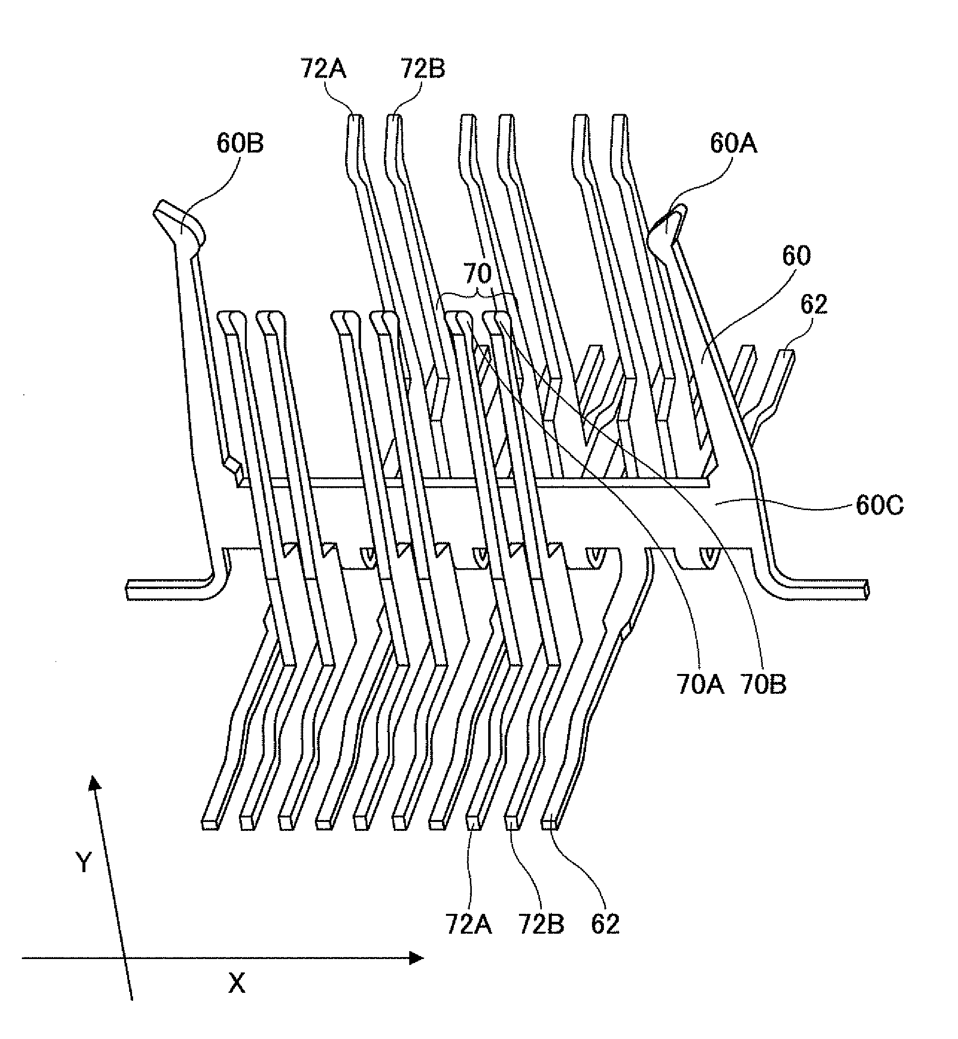
[0057]FIG. 9 is a perspective view illustrating conductor parts of the plug connector in a second embodiment of the present invention. Signal contacts of a plug connector 110 in this embodiment may be the same as that of the first embodiment described above, and thus, illustration and description thereof will be omitted. A (first) ground contact 120 illustrated in FIG. 9 may be formed by a conductor material which may be selected from metals including metals suited for the balanced transmission.

[0058]The ground contact 120 is formed by a plate-shaped member extending in the longitudinal direction (X) of the plug connector 110, and a plurality of slits 124 are formed in the plate-shaped member, as illustrated in FIG. 9. Of course, the plate-shaped member may only include a single slit 124. A plurality of lead parts 122 alternately extend towards mutually opposite s...


PUM


Abstract

A connector includes a ground contact formed by a plate-shaped conductor member extending in a longitudinal direction of the connector, and a plurality of signal contact pairs arranged on both sides of the ground contact, with two signal contacts forming each signal contact pair arranged side by side along the longitudinal direction. The ground contact may include a plurality of first lead parts alternately extending towards mutually opposite sides of the plate-shaped conductor member.

Description

CROSS-REFERENCE TO RELATED APPLICATIONS[0001]This application is based upon and claims the benefit of priority of the prior Japanese Patent Application No. 2009-237856, filed on Oct. 15, 2009, the entire contents of which are incorporated herein by reference.BACKGROUND OF THE INVENTION[0002]1. Field of the Invention[0003]The present invention relates to connectors and connector combination which may be suited for balanced transmission.[0004]2. Description of the Related Art[0005]When transmitting data among computers, peripheral equipments, circuit boards, and the like, either the unbalanced transmission or the balanced transmission may be employed. The unbalanced transmission transmits the data by a signal voltage with respect to a ground potential. On the other hand, the balanced transmission transmits the data by differential signals using a potential difference between a signal pair. The balanced transmission is employed in various fields because the balanced transmission is les...

Claims


Application Information

Patent Timeline
Patent Type & Authority Patents(United States)
IPC IPC(8): H01R13/648
CPCH01R12/716H01R13/6471H01R13/6587
Inventor KUMAMOTO, TADASHIOKUYAMA, TAKESHIYAMAKAMI, TORU
Owner FUJITSU COMPONENENT LTD
Why Eureka
Try Eureka