Decoupled vibration damper

a damper and decoupling technology, applied in the direction of spring/damper, rotating vibration suppression, rotary machine parts, etc., can solve the problems of increasing the parasitic inertia of the system, torsional vibrations of considerable amplitude, and fatigue failure of the rotatable shaft, etc., and achieve the effect of dampening vibration

Active Publication Date: 2012-01-10
DAYCO IP HLDG
View PDF36 Cites 14 Cited by
  • Summary
  • Abstract
  • Description
  • Claims
  • Application Information

AI Technical Summary

Benefits of technology

[0008]The present invention is premised on the realization that a torsional vibration damper suitable for automotive applications, as well as others, can be formed with an integral hub / inertia mass structure. The inner hub is connected to the inertia ring by a series of spokes which, in turn, lead to one or more intermediate rings or webs connected, in turn, to the inertia ring by outer spokes. This provides regions or windows between the hub and the intermediate web, as well as between the web and the inertia ring. The spokes and web are designed to flex and / or deform in use. At least some of the windows can be filled with elastomeric members that provide the dashpot. The dashpots are forced into these windows and held in position by pressure that they exert on the spokes and web. The bending of the spokes and web deforms the windows and the elastomeric inserts and thereby dampen vibration.
[0009]This design allows the inertia ring grooves and the hub bore to be machined in a single operation, thereby eliminating the run-out issues seen in the assembly of traditional torsional vibration dampers.
[0010]Also, the design allows the damper to be formed from a composite with an annular mass embedded in the composite damper.

Problems solved by technology

The torsional vibrations may be of considerable amplitude, and, if not abated, can potentially damage gears or similar structures attached to the rotatable shaft and cause fatigue failure of the rotatable shaft.
There are several design problems with these dampers.
Further, the hub of the damper adds parasitic inertia to the system.
This otherwise implies that the hub is, in fact, a rigid attachment that does not provide any significant help to the damping system except to provide a rigid means of connection to the rotating component of the vehicle.
This inherently causes a shear strain buildup in the elastomer.

Method used


Image

  • Decoupled vibration damper
  • Decoupled vibration damper
  • Decoupled vibration damper

Examples


Embodiment Construction

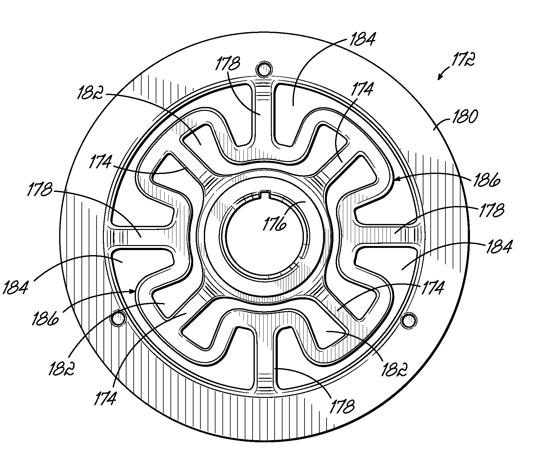
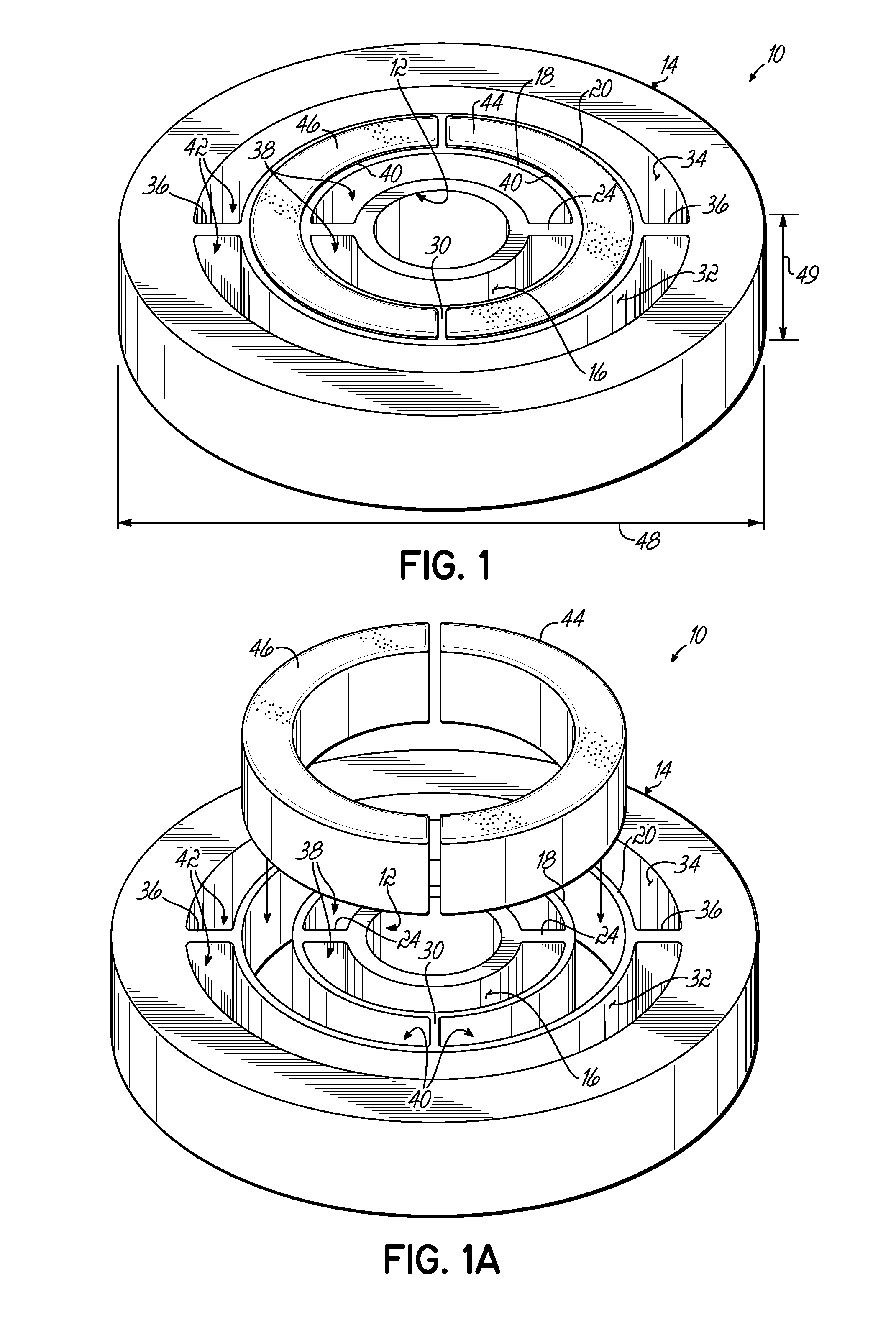
[0025]As shown in FIG. 1, the present invention is a damper 10 that includes a hub 12 and an outer annular inertia mass 14 formed integrally with the hub. Between the outer peripheral surface 16 of hub 12 and the inertia mass 14 are a first inner ring 18 and a second intermediate ring 20. The first inner ring 18 is connected to the outer surface 16 of hub 12 by first innermost spokes 24 which extend from the inner surface 22 of ring 18 to the outer surface 16 of hub 12. Extended between the outer surface 26 of ring 18 and the inner surface 28 of ring 20, are a second set of intermediate spokes 30, which connect the inner ring 18 to the intermediate ring 20. Finally, extended between the outer surface 32 of ring 20 to the inner surface 34 of inertia mass 14, are a third set of outer spokes 36. Preferably, the hub 12, inertia mass 14, as well as rings 18 and 20 and spokes 24, 30 and 36, are all integrally formed.

[0026]This structure defines innermost arcuate spaces 38 between the hub ...


PUM


Abstract

A torsional vibration damper includes a one-piece integral hub and annular inertia mass assembly. Between the hub and the inertia mass are intermediate rings connected integrally with the mass and the hub connected integral spokes. Elastomeric members are compression fitted within spaces formed between the hub and the mass. With this design, the damper can be formed from a polymeric material with an embedded annular weight.

Description

RELATED APPLICATION[0001]This application is a continuation-in-part application of U.S. patent application Ser. No. 11 / 861,921, filed on Sep. 26, 2007. The entire disclosure of this earlier-filed application is incorporated herein by reference.BACKGROUND OF THE INVENTION[0002]Torsional vibration dampers are employed extensively in internal combustion engines to reduce torsional vibrations delivered to rotatable shafts. The torsional vibrations may be of considerable amplitude, and, if not abated, can potentially damage gears or similar structures attached to the rotatable shaft and cause fatigue failure of the rotatable shaft.[0003]Torsional vibration dampers convert the kinetic vibrational energy by dissipating it to thermal energy as a result of damping. The absorption of the vibrational energy lowers the strength requirements of the rotatable shaft and thereby lowers the required weight of the shaft. The torsional vibration damper also has a direct effect on inhibiting vibration ...

Claims


Application Information

Patent Timeline
Patent Type & Authority Patents(United States)
IPC IPC(8): F16C15/00F16F15/12F16D3/00
CPCF16F15/1428F16F15/1442Y10T74/2131Y10T74/2121
Inventor MANZOOR, SUHALECHRISTENSON, BRUCE G.
Owner DAYCO IP HLDG
Why Eureka
Try Eureka