Method of manufacturing spark plug

a manufacturing method and technology of spark plugs, applied in the manufacture of spark plugs, spark plugs, electrical equipment, etc., can solve the problems of insulator breakage, high risk of breakage, and large stress on the insulator, so as to reduce the speed at which the terminal electrode is inserted between the start and the end of the second process, reduce the load on the insulator, and reduce the speed of the terminal electrode insertion.

Active Publication Date: 2012-01-10
NGK SPARK PLUG CO LTD
View PDF7 Cites 2 Cited by
  • Summary
  • Abstract
  • Description
  • Claims
  • Application Information

AI Technical Summary

Benefits of technology

[0012]According to the manufacturing method of the invention, in the second process for compacting the first to third powder materials by the terminal electrode, the degree of compaction of the first to third powder materials increases as the end of the process gets closer, and the load exerted on the insulator increases. In this aspect, the speed at which the terminal electrode is inserted between the start and the end of the second process is reduced. That is, while the degree of compaction of the powder materials is low, there is no concern of breakage since the load exerted on the insulator is low, so that the degradation of productivity is suppressed by increasing the insertion speed of the terminal electrode. Then, when the degree of compaction of the powder materials is increased as the compaction step progresses, the increase in the load exerted on the insulator is suppressed by decreasing the insertion speed of the terminal electrode, thereby avoiding insulator breakage.
[0013]As described above, according to the invention, the decrease in yield and the degradation of productivity can be simultaneously avoided. Particularly, when attempts are made to decrease the size and diameter of the spark plug, the thickness of the insulator is reduced, and there is a concern regarding the degradation of mechanical strength. On this point, the manufacturing method according to the invention is effective.

Problems solved by technology

In the case where the spark plug is manufactured as described above, since the first to third powder materials are compacted by the terminal electrode in the second process, a large amount of stress occurs in the insulator.
Therefore, there is a concern that the insulator will suffer breakage.
As a result, the danger of this happening (i.e., breakage) is particularly high.
However, in this case, although the decrease in yield due to breakage can be avoided, the time needed for the second process increases, so that productivity is degraded.

Method used


Image

  • Method of manufacturing spark plug
  • Method of manufacturing spark plug
  • Method of manufacturing spark plug

Examples


first embodiment

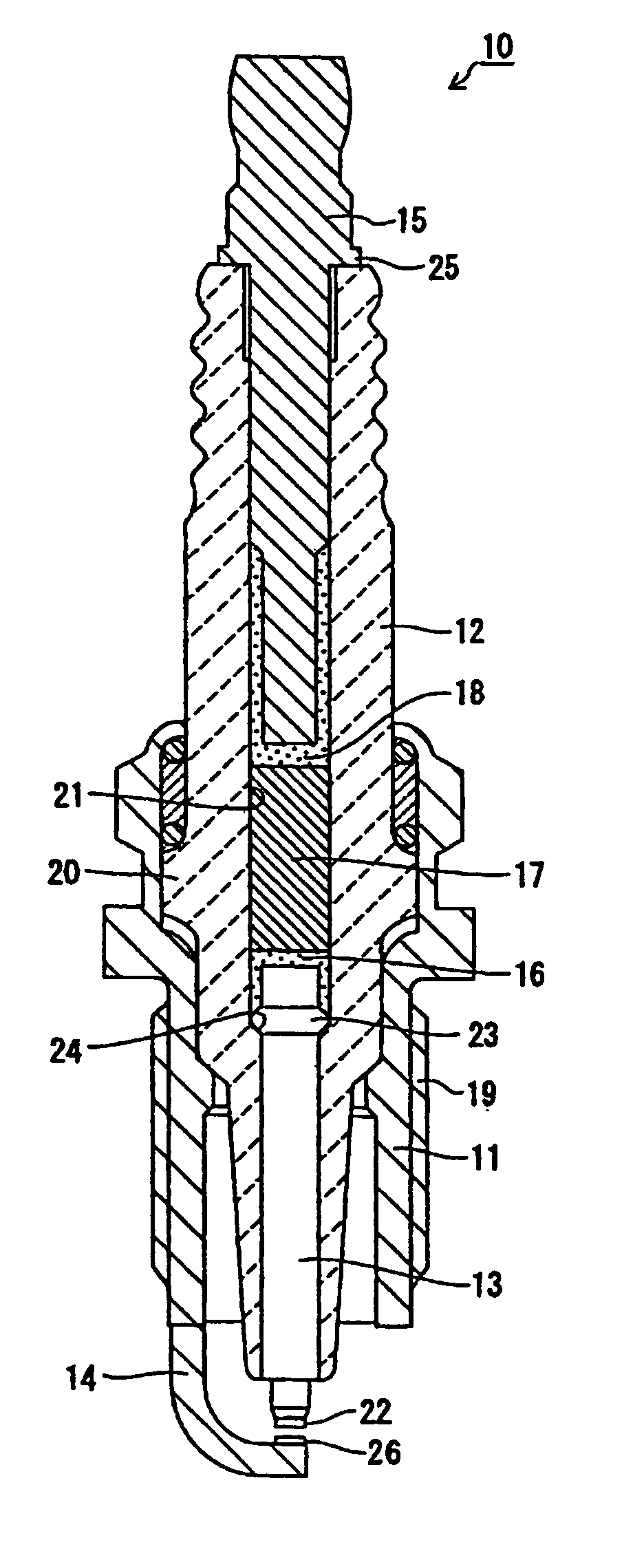
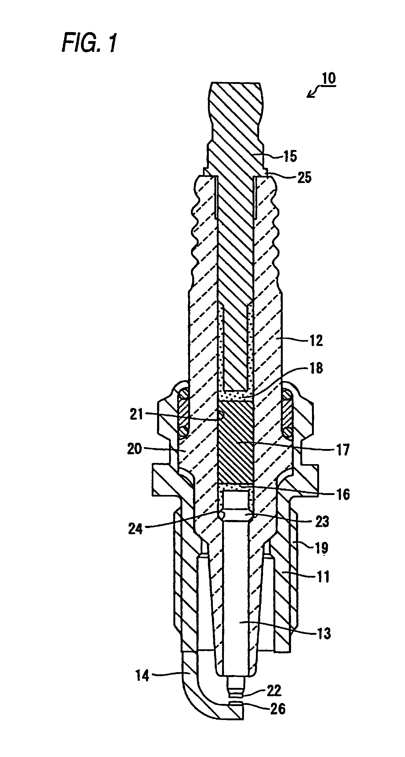
[0029]Hereinafter, a first embodiment of the invention will be described with reference to FIGS. 1 to 5. A spark plug 10 of this embodiment illustrated in FIG. 1 includes a metal shell 11, an insulator 12, a center electrode 13, a ground electrode 14, a terminal electrode 15, a first conductive sealing material layer 16, a resistor 17, and a second conductive sealing material layer 18. In addition, in the following description, with respect to the upward and downward directions of the spark plug 10, a lower end in FIG. 1 is referred to as a leading end, and an upper end thereof is referred to as a rear end.

[0030]The metal shell 11 has a cylindrical shape with a hole penetrating vertically and is provided with a male thread 19 at its outer periphery for mounting the spark plug 10 to an engine block not shown. The insulator 12 is accommodated in the metal shell 11 such that its leading end portion protrudes from the metal shell 11. The insulator 12 has a hole penetrating vertically an...

second embodiment

[0062]Next, a second embodiment of the invention will be described with reference to FIGS. 6 and 7. According to the second embodiment, the control method for changing the insertion speed of the terminal electrode 15 in the first step and the second step from the high speed to the low speed is different from that of the first embodiment, and a press apparatus 50 has a different configuration from that of the press apparatus 30 of the first embodiment according to this control method. Since other elements are the same as those of the first embodiment, like elements are denoted by like reference numerals, and a description of the structures, the operations, and the effects thereof will be omitted.

[0063]In the press apparatus 50 according to the second embodiment, as illustrated in FIG. 6, a load cell 51 is mounted to the lower end of the press pin 43, and a pressing surface 52 at the lower end of the load cell 51 presses the upper end surface (rear end surface) of the terminal electro...


PUM

PropertyMeasurementUnit
temperatureaaaaaaaaaa
speedaaaaaaaaaa
speedaaaaaaaaaa

Abstract

A decrease in yield and degradation of productivity can be avoided when a spark plug having an insulator with low mechanical strength is manufactured. In a second process, a terminal electrode 15 is inserted to a predetermined position in a state where an insulator 12 is heated to a temperature equal to or greater than the softening temperatures of first to third powder materials 16P, 17P, and 18P such that the first powder material 16P becomes a first conductive sealing material layer 16, the second powder material 17P becomes a resistor 17, and the third powder material 18P becomes a second conductive sealing material layer 18. In addition, a speed at which the terminal electrode 15 is inserted is reduced between the start and the end of the second process.

Description

TECHNICAL FIELD[0001]The present invention relates to a method for manufacturing a spark plug.BACKGROUND ART[0002]A manufacturing method of a spark plug is disclosed in Patent Document No. JP-A-2005-340171. The spark plug has a configuration including an insulator having a through-hole in an axial direction, a center electrode inserted into and fixed to a leading end side of the through-hole, a terminal electrode inserted into and fixed to a rear end side of the through-hole, a first conductive sealing material layer fixed to the center electrode in the through-hole, a second conductive sealing material layer fixed to the terminal electrode in the through-hole, and a resistor interposed between the first conductive sealing material layer and the second conductive sealing material layer in the through-hole and fixed to both conductive sealing material layers.[0003]The spark plug is manufactured by the following two processes. First, in the first process, after inserting the center el...

Claims


Application Information

Patent Timeline
Patent Type & Authority Patents(United States)
IPC IPC(8): H01T21/02H01T21/00
CPCH01T13/34H01T21/02
Inventor SHIBATA, TSUTOMUKATO, RYOJITSUKADA, ATSUSHI
Owner NGK SPARK PLUG CO LTD
Why Eureka
Try Eureka