Self retained electrical device having positive locking mechanism
a technology of locking mechanism and self-retention, which is applied in the direction of coupling device connection, electrical apparatus casing/cabinet/drawer, instruments, etc., can solve the problems of not having the ability to retain an electrical plug in the outlet, the type of cover is expensive, and the type of safety device does not have a positive locking featur
- Summary
- Abstract
- Description
- Claims
- Application Information
AI Technical Summary
Benefits of technology
Problems solved by technology
Method used
Image
Examples
first embodiment
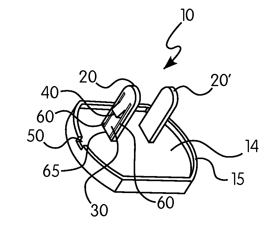
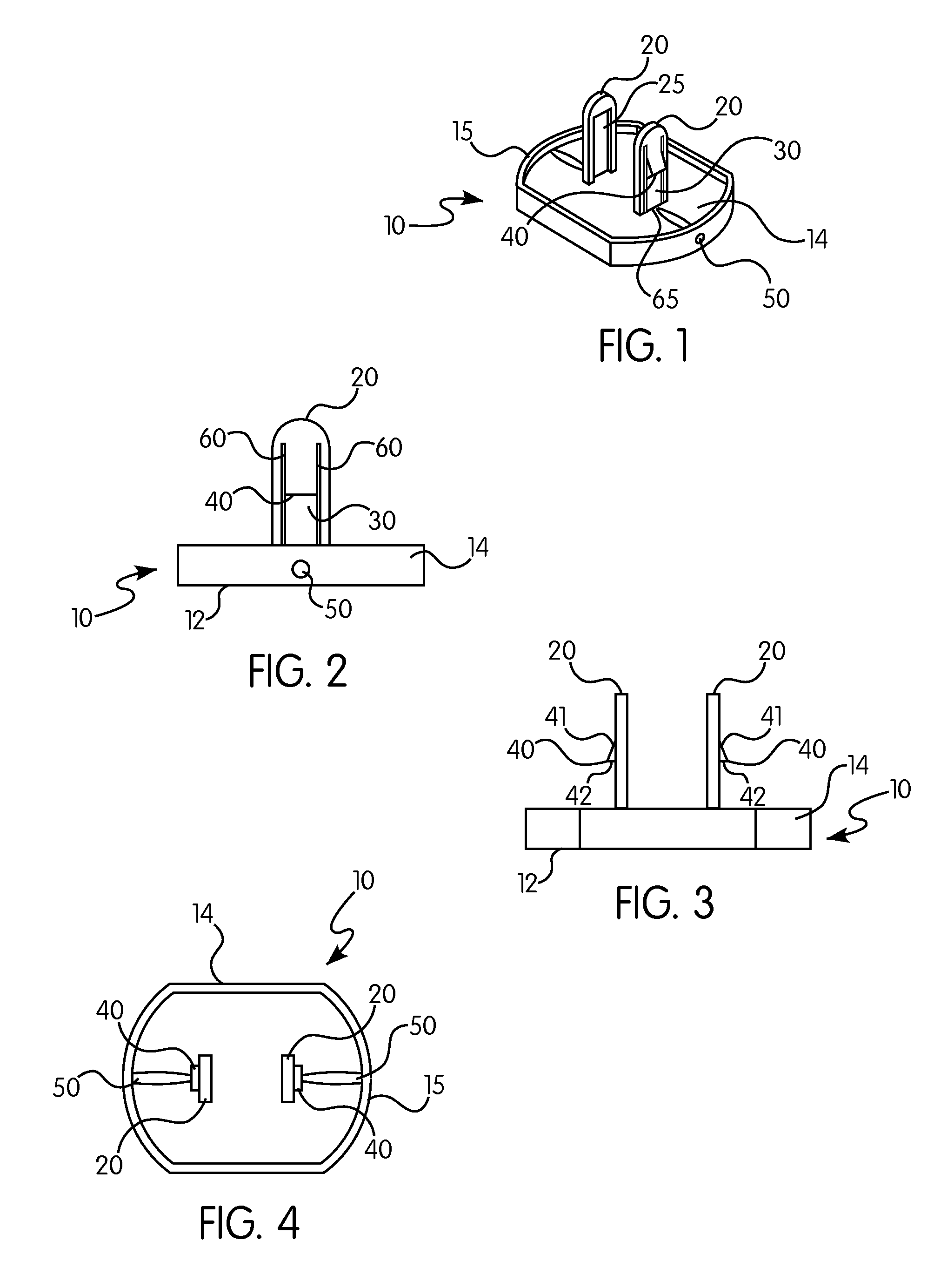
[0058]FIGS. 1-4 show the protective cover 10 of the present invention. Protective cover 10 has main body 14 defining rim 15 around the rear perimeter thereof. Main body 14 has two prongs 20 extending from the rear surface thereof, each of prongs 20 defining a reverse tongue 30 with barbs 40. Reverse tongues 30 are relieved from prongs 20 on either side with slits 60 and on the lower end thereof with slit 65. Tongue 30 is also relieved on the inside surface 25, having a thinner cross sectional area than the remainder of prong 20, to allow barbs 40 to deflect within the width of prong 20 while being inserted into an electrical outlet.
[0059]Ramped surfaces 41 on one side of barbs 40 cause the deflection of tongue 30 during insertion of the device, and allows barbs 40 to fit within the width of the rectangular openings on the outlet. When prongs 20 have been fully inserted into a typical electrical outlet, tongues 40 will rebound to their original position, allowing the flat surface 42 ...
second embodiment
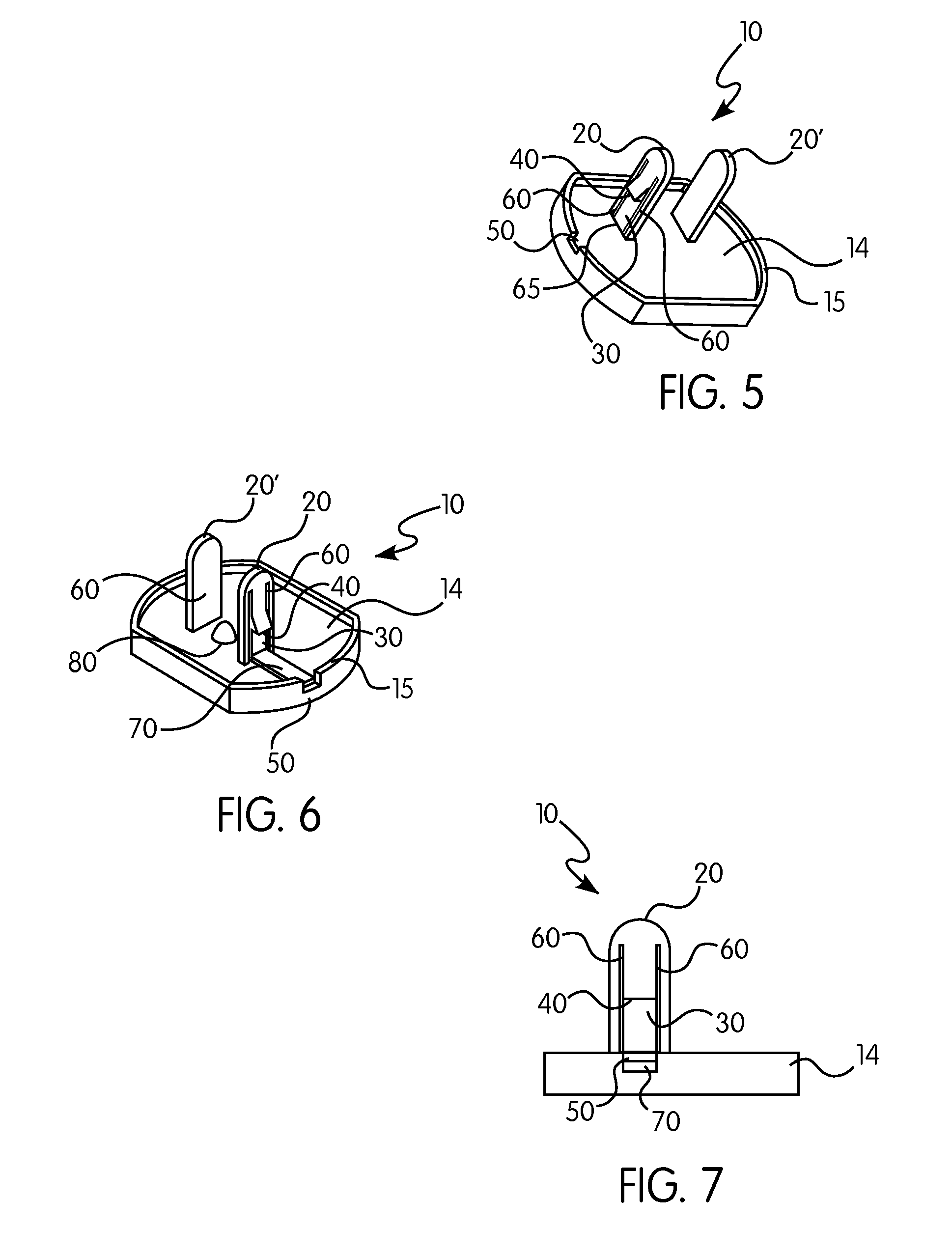
[0062]FIGS. 6-8 show the invention. In many aspects, this embodiment is essentially identical to the embodiment shown in FIG. 1. The main difference is the presence of tab 70 that protrudes through or is accessible through opening 50 defined in rim 15. Tab 70 may be pressed from the outside of protective cover 10 to disengage barb 40 from the rear surface of the outlet. Tab 70 may protrude slightly through rim 15, or may be slightly recessed within the rim. Note that, for tab 70 to work properly, tab 70 must be able to slide freely back and forth, and must therefore remain offset from the outlet. Post 80, located between prongs 20 and 20′ serves to keep the body of device 10 from pressing tab 70 into the surface of the outlet.
[0063]As with the embodiments shown in FIGS. 1-5, all variations as discussed above with respect to the embodiment of FIGS. 1-5 are contemplated to be applicable to this embodiment as well.
third embodiment
[0064]FIGS. 9-10 shows the invention in which protective cover 10 is configured with barbs 40 having a slightly different shape than those of previous embodiments. In this embodiment, rim 15 has no openings, as tongues 40 need not be deflected using external means to effect removal of the device. Instead, in this embodiment, barbs 40 have two ramped surfaces 41 and 42, and tongues 30 are only relieved from prongs 20 on their sides by slots 60. Additional slot 65 is not present on the bottom of tongues 30, as with other embodiments. To remove protective cover 10 having this design, additional pulling force is required, as tongue 30 will be more difficult to deflect. Ramped edge 42 defined on barb 40 will deflect tongue 30 inwardly until barb 40 is released from the rear surface of the outlet.
[0065]Variations on this embodiment (not shown) are similar to those for the embodiments shown in FIGS. 1-8, including having only one prong 20 having a tongue 30 define therein and one solid pro...
PUM
 Abstract
Description
Claims
Application Information
 - R&D
- Intellectual Property
- Life Sciences
- Materials
- Tech Scout
- Unparalleled Data Quality
- Higher Quality Content
- 60% Fewer Hallucinations
Browse by: Latest US Patents, China's latest patents, Technical Efficacy Thesaurus, Application Domain, Technology Topic, Popular Technical Reports.
© 2025 PatSnap. All rights reserved.Legal|Privacy policy|Modern Slavery Act Transparency Statement|Sitemap|About US| Contact US: help@patsnap.com


