
Removable and replaceable modular optic package with controlled microenvironment

Active Publication Date: 2012-01-10
LIGHT SOURCE SYST INC
View PDF11 Cites 1 Cited by
  • Summary
  • Abstract
  • Description
  • Claims
  • Application Information

AI Technical Summary

Benefits of technology

[0006]The present invention pertains generally to a combination of optical elements integrated into a singular unit to perform one or more functional operations upon an electromagnetic radiation emission conveyed through said unit, and more particularly, a plurality of optical elements that are durably integrated into a modular optical package, wherein said modular optical package is adaptive to a releasable mounting mechanism and has the capability to maintain an independently controlled microenvironment. An electromagnetic radiation emission in introduced into, and is an integral part of, the modular optical package through at least one ingress portal and upon modification by the internal optical elements, exits the modular optical package through at least one egress portal. Optical elements included in the modular optical package are selected from such devices as may have an effect on the qualities of a light source emitted into the modular optical package, including such elements as one or more lens, prisms, filters, grat

Problems solved by technology

Optical elements used in modifying high energy light are extremely sensitive to orientation, thermal stress, and contamination of the light receiving / emitting surfaces.
Slight deviations in one or more of the optical elements conducting a light pathway will cause at the least a significant degradation in the desired modification of that light energy and in most cases will cause complete failure of the light energy to be conveyed through the modification pathway.
Thermal stress have multiple deleterious effects on a modification pathway, including distancing and orientation shifts which have the potential to induce the slight deviation mentioned previously, as well as inducing physical stresses in the optical elements themselves which degrade the operational lifespan of the overall system.
Further, an obstruction to the optical clarity of the optical elements themselves will degrade the performance of modification pathway.
Obstructions to optical clarity typically include opaque occlusions (e.g. dust, dirt, and lint) which settle on the optical surfaces and performance degradants (e.g. out-gassing volatiles, aerosolized liquids, and condensing oils) which accumulate on the surface and modify the reflective, refractive, and / or transmission values thereof.
These violet and ultraviolet wavelengths have a tendency to “plate these contaminants” onto the surfaces of the optical pathway and thus, severely degrading the transmission properties.
The need for optical modification pathways, along with the associated environmental control processing and hardware has led to current optoelectronic packages being large, expensive, and difficult to both manufacture and maintain.
Furthermore, the costs associated with initial manufacture and subsequent maintenance has resulted in significant capital outlays necessary to procure such equipment.
The aforementioned enclosed laser-based optical packages met to a limited degree the functionality requirements needed in an optical modification pathway.

Method used


Image

  • Removable and replaceable modular optic package with controlled microenvironment
  • Removable and replaceable modular optic package with controlled microenvironment
  • Removable and replaceable modular optic package with controlled microenvironment

Examples


Embodiment Construction

[0022]While the present invention is susceptible of embodiment in various forms, there is shown in the drawings and will hereinafter be described a presently preferred embodiment of the invention, with the understanding that the present disclosure is to be considered as an exemplification of the invention, and is not intended to limit the invention to the specific embodiment illustrated.

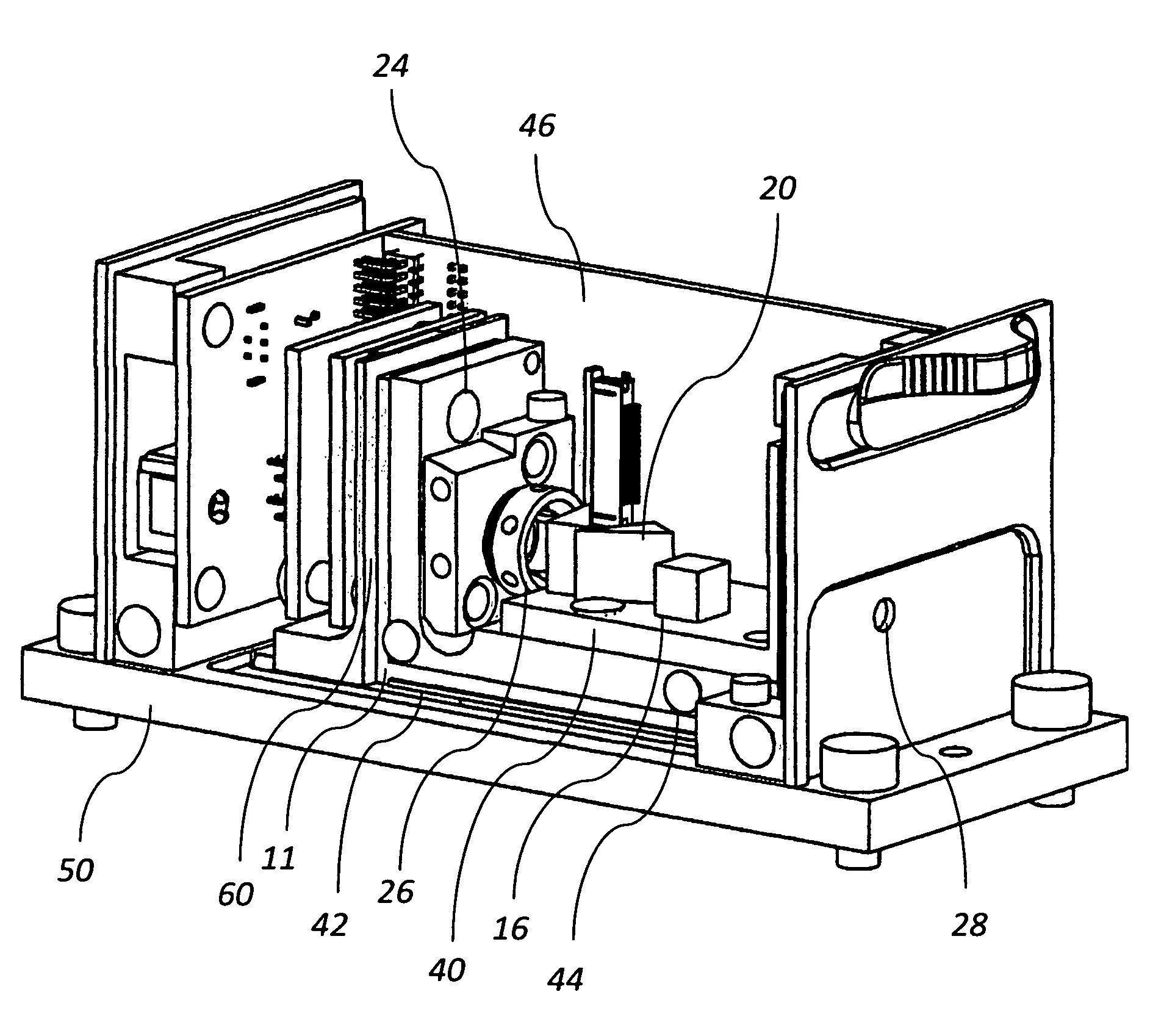
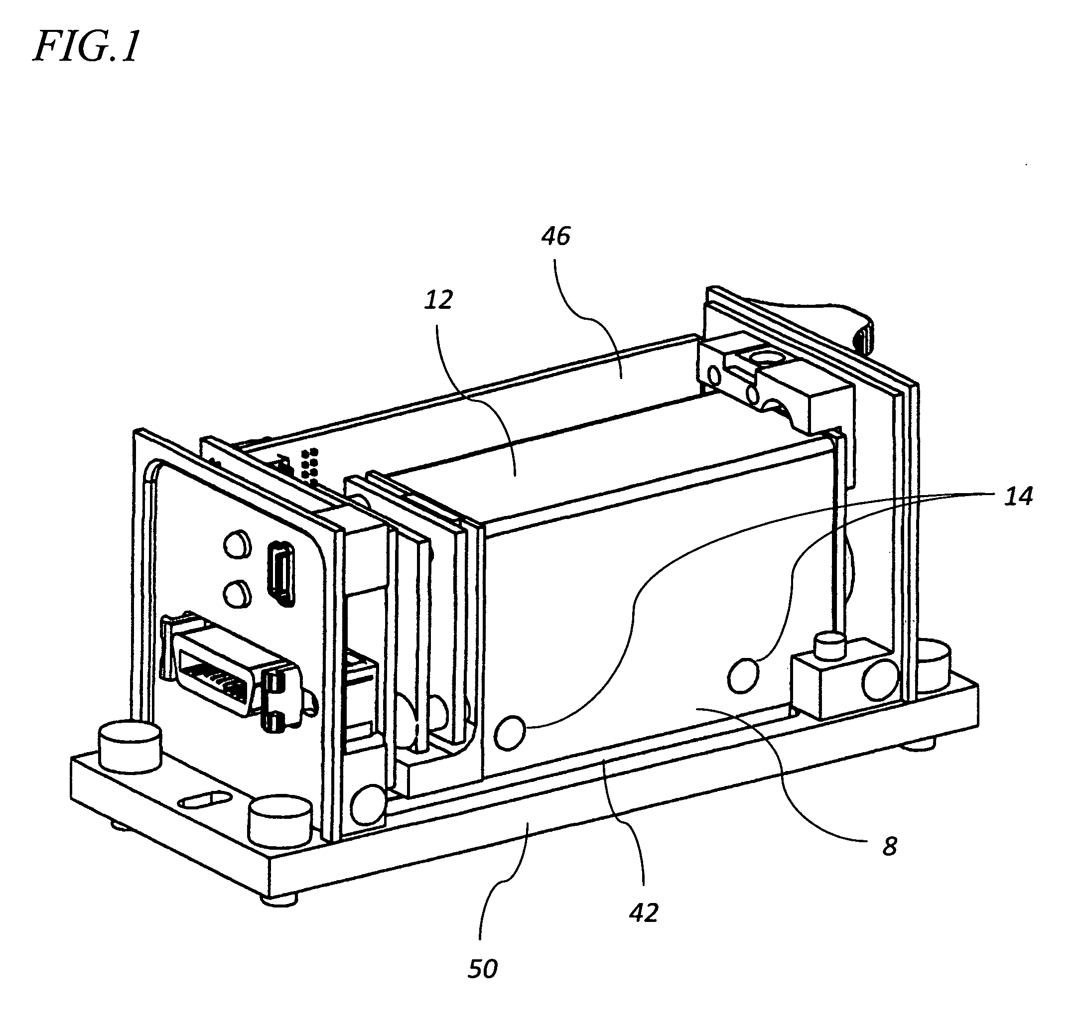
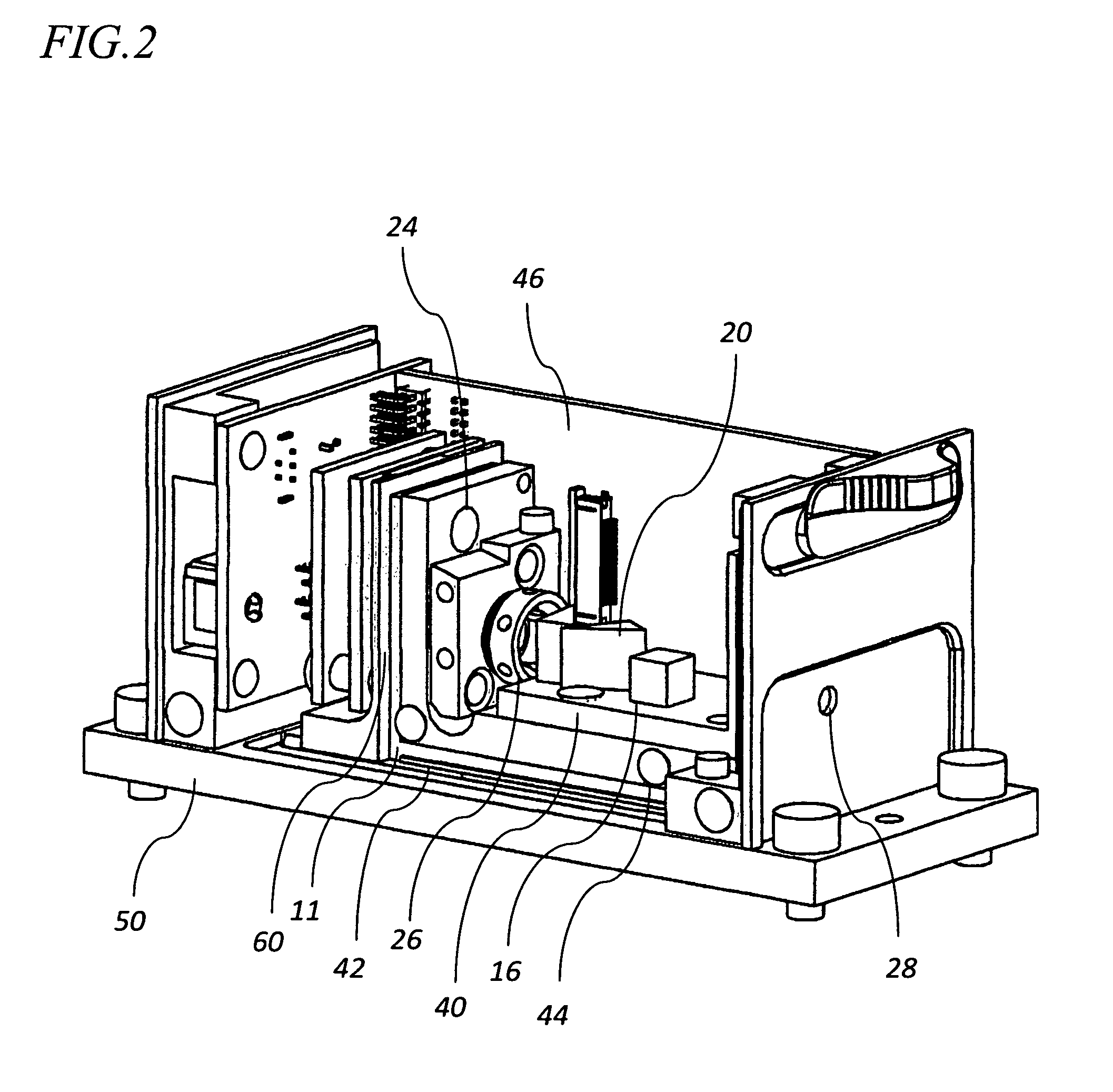
[0023]The inventors have identified a distinct advantage is employing a modular optical package concept by combining an emission device and the associated electronic circuitry (including one or more dynamic feedback sensors) to desired optical modification elements by which to alter the emission from the emission device. It is acknowledged in the art that optical alignment and stability against thermal and physical shock it of paramount importance in such devices where slight misalignment can greatly comprise the usefulness of an emission device. However, unlike prior art assemblies which have relied...


PUM


Abstract

The present invention pertains generally to a combination of optical elements integrated into a singular unit to perform one or more functional operations upon an electromagnetic radiation emission conveyed through said unit, and more particularly, a plurality of optical elements that are durably integrated into a modular optical package, wherein said modular optical package is adaptive to a releasable mounting mechanism and has the capability to maintain an independently controlled microenvironment. An electromagnetic radiation emission in introduced into the modular optical package through at least one ingress portal and upon modification by the internal optical elements, exits the modular optical package through at least one egress portal. A microenvironment is maintained within the enclosure of the modular optical package such that humidity, temperature, atmospheric composition, particulates, and out-gassing contaminants are controlled.

Description

PARENT CASE TEXT[0001]This application claims the benefit under 35 U.S.C. 119(e) of U.S. provisional application Ser. No. 61 / 204,937 filed Jan. 12, 2009, which is incorporated by reference herein in its entirety.BACKGROUND[0002]Electromagnetic radiation sources are often employed in providing high energy light (i.e. coherent or laser light) to medical, scientific, and projection equipment. Such high energy light often requires modification of the wave pattern, focus, beam shape, or other attribute in order to render the light in an optimal usable form by the equipment. Modification of the high energy light is often performed by optical elements positioned intermediate to the electromagnetic radiation source and the equipment that subsequently will utilize that light in its respective operation. The optical elements act upon the light as it is emitted upon and / or passes through the elements, with such action occurring in serial and / or parallel optical modification steps.[0003]Optical...

Claims


Application Information

Patent Timeline
IPC IPC(8): G02B7/02H01L31/0203
CPCG02B7/008H01L31/0203H01L31/0232H01L31/02325
Inventor WILNER, DOUGKRUGER, CHRISWILLIAMS, GERALDTHOMSON, GLEN
Owner LIGHT SOURCE SYST INC
Learn More