Sound source separating apparatus and sound source separating method

a technology of sound source and separation apparatus, which is applied in the direction of noise generation, ear treatment, instruments, etc., can solve the problem of inability to separate the two sounds to be displayed, and achieve the effect of reducing the development period of a noise-free product, effective and rapid implementation of oscillation and noise control

Inactive Publication Date: 2012-01-10
HITACHI LTD
View PDF5 Cites 4 Cited by
  • Summary
  • Abstract
  • Description
  • Claims
  • Application Information

AI Technical Summary

Benefits of technology

[0006]An object of the present invention is to provide a sound source separating apparatus and a sound source separating method for enabling effective and rapid implementation of oscillation and noise control and reduction in development period of a noise-free product by separating into a fluid sound component and an oscillation sound component for output.
[0019]According to a sound source separating apparatus and a sound source separating method of the present invention, it is possible to effectively and rapidly implement oscillation and noise control and reduce a development period of a noise-free product by separating into a fluid sound component and an oscillation sound component for output.

Problems solved by technology

However, in the above-described sound source survey method, fluid sound (e.g., blade sound generated when a propeller rotates) due to fluctuations in fluid pressure and oscillation sound (e.g., electromagnetic sound generated by oscillation of a motor) due to oscillation of a structure are mixed and displayed on identified sound pressure distribution, and thus it is impossible to separate the both sound to be displayed.

Method used


Image

  • Sound source separating apparatus and sound source separating method
  • Sound source separating apparatus and sound source separating method
  • Sound source separating apparatus and sound source separating method

Examples


first embodiment

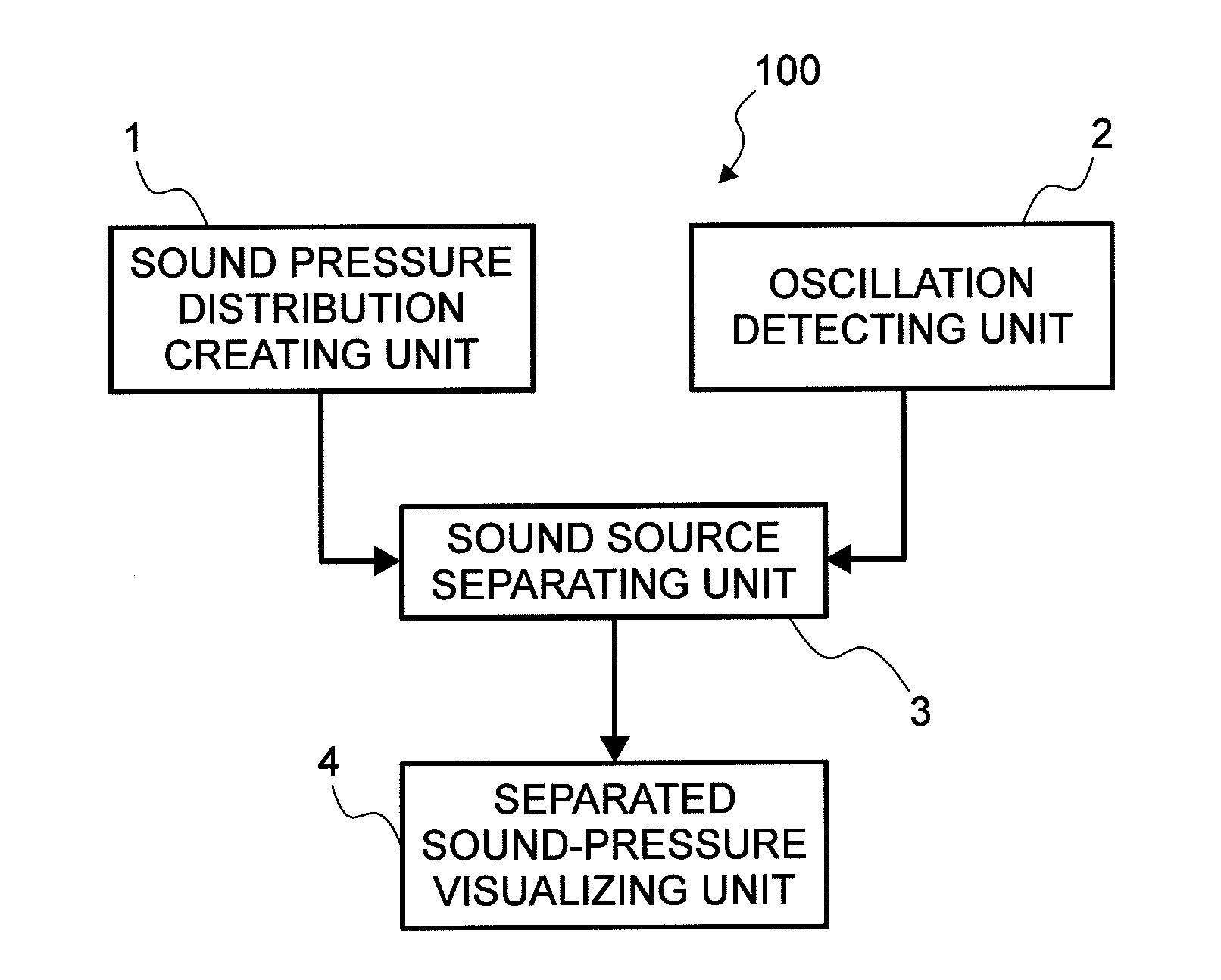
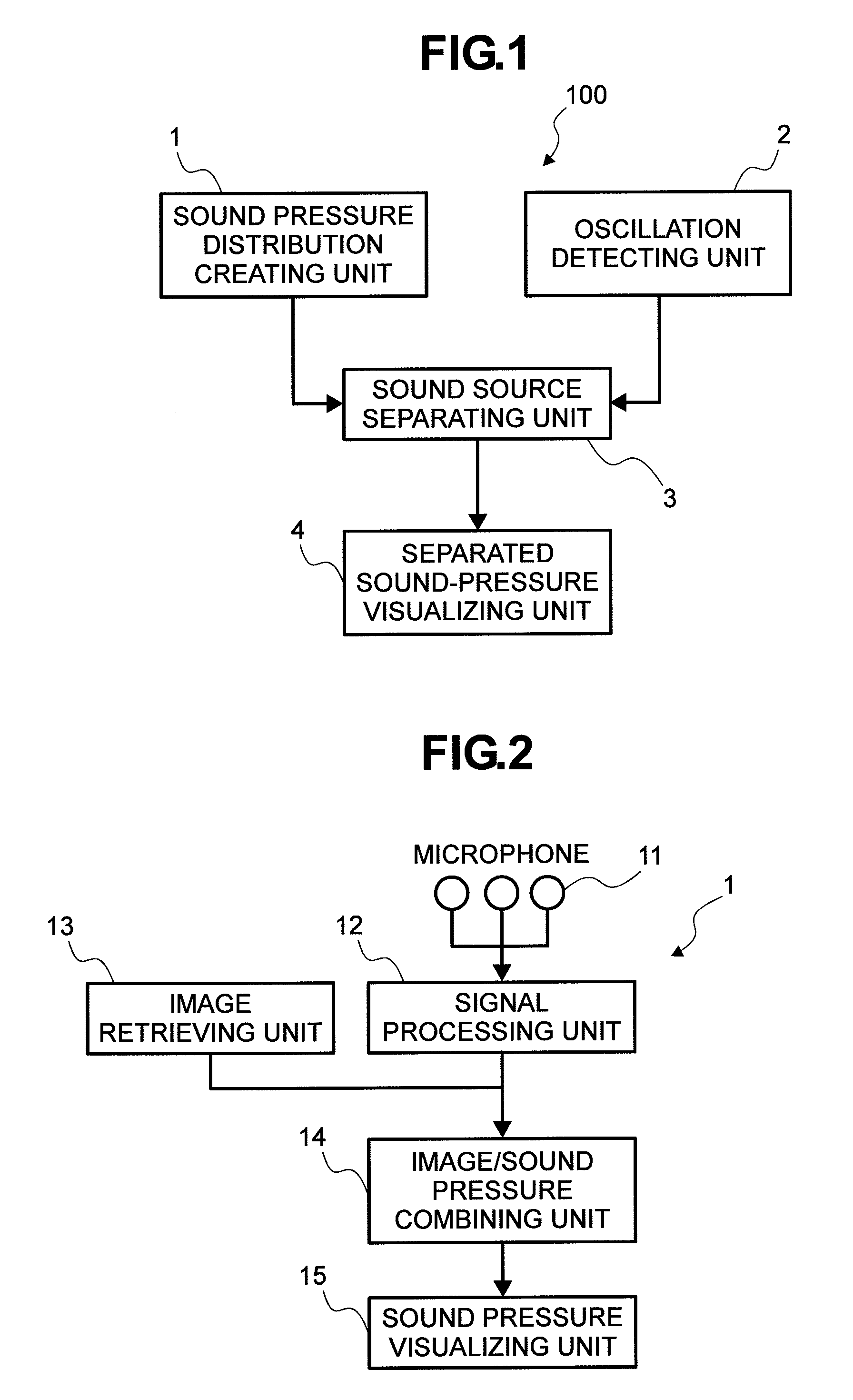
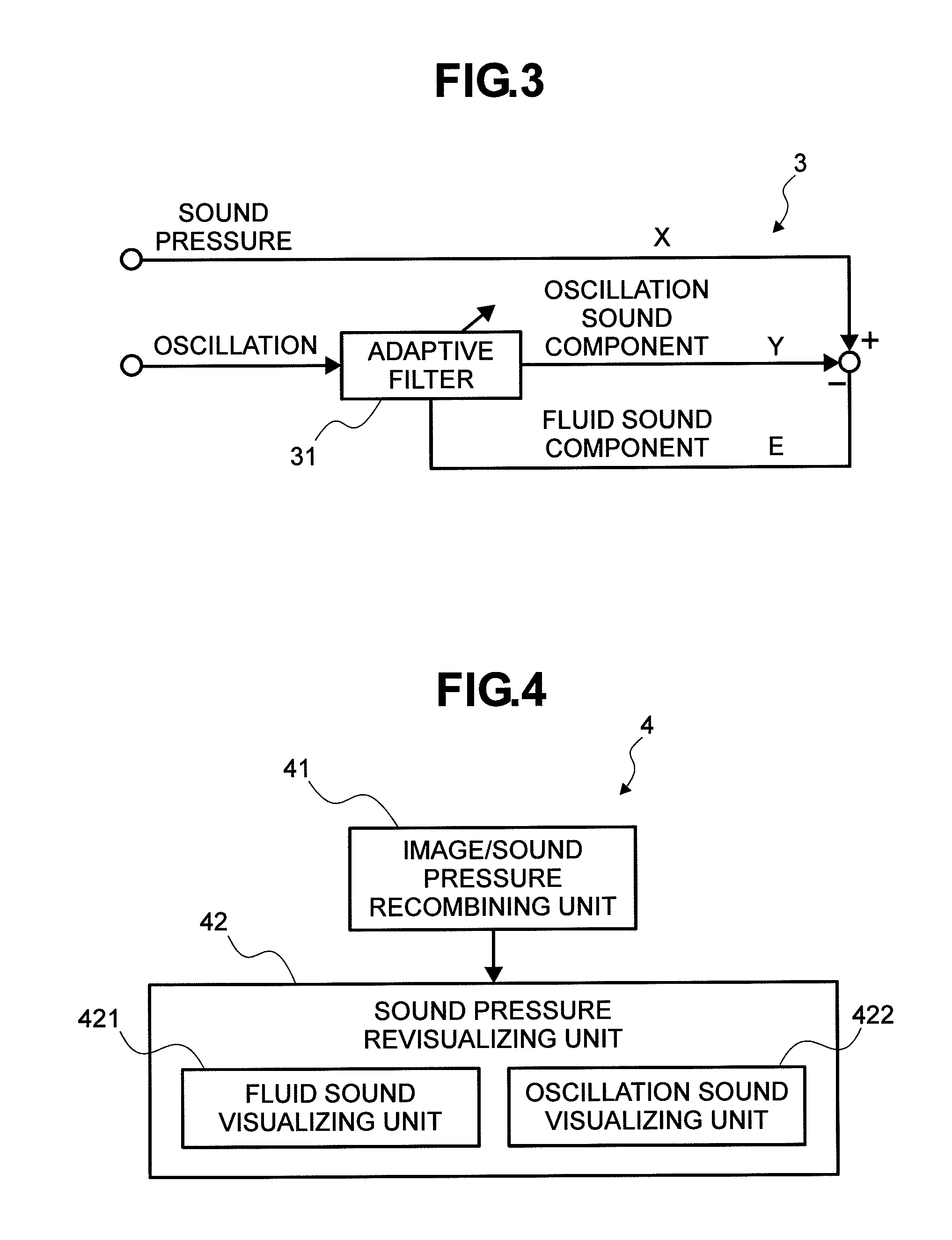
[0027]A first embodiment of the present invention will be described using FIGS. 1 to 4. FIG. 1 is a block diagram of a sound source separating apparatus 100 of the first embodiment, FIG. 2 is a block diagram of a sound pressure distribution creating unit 1 in FIG. 1, FIG. 3 is a block diagram of a sound source separating unit 3 in FIG. 1, and FIG. 4 is a block diagram of a separated sound-pressure visualizing unit 4 in FIG. 1.

[0028]The sound source separating apparatus 100 includes the sound pressure distribution creating unit 1, an oscillation detecting unit 2, the sound source separating unit 3, and the separated sound-pressure visualizing unit 4, as shown in FIG. 1.

[0029]The sound pressure distribution creating unit 1 creates and visualizes sound pressure distribution in which both of air sound (fluid sound) and solid sound (oscillation sound) are mixed. Here, the air sound is defined as fluid sound (e.g., blade sound generated when a propeller rotates) which is generated due to ...

second embodiment

[0038]Next, a second embodiment of the present invention will be described using FIG. 5. FIG. 5 is a block diagram of a sound source separating apparatus according to the second embodiment of the present invention. It should be noted that the second embodiment is different from the first embodiment in the following points, but is basically the same as the first embodiment in the other points, and thus the overlapped explanation will not be repeated.

[0039]In the first embodiment, there has been described a case in which the sound sources are the fluid sound of one kind and the oscillation sound of one kind. However, the present invention is effective in the case where the kind of fluid sound and oscillation sound increases to plural kinds. The second embodiment is an embodiment corresponding to a case in which the kind of fluid sound and oscillation sound increases to plural kinds. FIG. 5 shows a block diagram of a case in which two kinds of fluid sound and two kinds of oscillation s...

third embodiment

[0041]Next, a third embodiment of the present invention will be described using FIG. 6. FIG. 6 is a block diagram of a sound source separating apparatus according to the third embodiment of the present invention. It should be noted that the third embodiment is different from the first embodiment in the following points, but is basically the same as the first embodiment in the other points, and thus the overlapped explanation will not be repeated.

[0042]In the third embodiment, a pressure detecting unit 5 is used in place of the oscillation detecting unit 2 of the first embodiment. Thus, the process in the sound source separating unit 3 is slightly different from that in the first embodiment. That is, the pressure of the fluid is used as a signal, so that the fluid sound component, not the oscillation sound component, is subtracted from the sound pressure distribution in which the fluid sound and the oscillation sound are mixed. The other configurations and processes are the same as t...


PUM


Abstract

There is disclosed a sound source separating apparatus (100) including: a sound pressure detecting unit which detects a sound pressure in which fluid sound generated due to fluctuations in fluid pressure and oscillation sound generated due to oscillation of a solid are mixed; an oscillation detecting unit (2) which detects oscillation of the solid; and a sound source separating unit (3) which separates the sound pressure detected by the sound pressure detecting unit into a fluid sound component and an oscillation sound component for output by using the sound pressure detected by the sound pressure detecting unit and the oscillation detected by the oscillation detecting unit (2). By separating into the fluid sound and the oscillation sound, it is possible to effectively and rapidly implement oscillation and noise control and reduce a development period of a noise-free product.

Description

FIELD OF THE INVENTION[0001]The present invention relates to a sound source separating apparatus and a sound source separating method, and is particularly suitable for a separating apparatus and a separating method of a sound source in which fluid sound generated due to fluctuations in fluid pressure and oscillation sound generated due to oscillation of a solid are mixed.BACKGROUND OF THE INVENTION[0002]As a conventional sound source survey method, sound source survey apparatuses have been developed and commercialized by various audio equipment manufacturers. The sound source survey apparatus is used for visualizing a sound pressure in such a manner that by using a microphone array composed of plural microphones arranged in various shapes, sound pressure distribution is computed at a certain distance on the basis of a sound pressure and phase detected by the microphone array in the principle of beam forming so as to be mapped to an image.[0003]Further, a conventional contribution di...

Claims


Application Information

Patent Timeline
Patent Type & Authority Patents(United States)
IPC IPC(8): G10K11/16
CPCG01H3/00G01S3/808
Inventor WATANABE, MASANORI
Owner HITACHI LTD
Why Eureka
Try Eureka