Heat radiator using heat pipe panel

a technology of heat pipe panel and radiator, which is applied in the direction of cosmonautic thermal protection, lighting and heating apparatus, cosmonautic vehicles, etc. it can solve the problems of heat radiation problem, difficult to apply the technique of standard satellite bus, and limited mounting area of heat generation apparatus, so as to reduce the temperature and prevent excessive temperature reduction. , the effect of reducing the development period

Active Publication Date: 2019-03-07
MITSUBISHI ELECTRIC CORP
View PDF0 Cites 1 Cited by
  • Summary
  • Abstract
  • Description
  • Claims
  • Application Information

AI Technical Summary

Benefits of technology

[0016]According to the present invention, the same thermal structure design and equipment layout design can be applied in design of the artificial satellite and the spacecraft even when apparatuses to be mounted or conditions of an orbit and attitude at the time of putting the satellite or the spacecraft differ, thereby obtaining advantages that mechanical system design is standardized and the development period and costs can be reduced. It is possible to use the same design in heat pipes, heat radiation surfaces and heaters particularly in thermal design even when heat input conditions vary due to differences in orbit and attitude conditions and in apparatuses to be mounted.
[0017]Moreover, inner panels on which apparatuses are mounted are thermally connected by heat pipes, therefore, if a certain apparatus is turned off and the temperature is reduced, excessive reduction in temperature can be prevented by heat generation of other apparatuses, and heat generation of apparatuses can be used as a heater, which can reduce the power for the heater and heater systems.

Problems solved by technology

However, it is difficult to apply the technique of the standardized satellite bus and the technique of the south-north connected heat pipes to a low orbit satellite or a spacecraft having different orbit and attitude conditions and not having a concept of the south and north surfaces though these technique may be applied to geostationary satellites in which heat input of solar light to the south and north surfaces is small.
As main heat radiation surfaces are limited to two surfaces that are south and north surfaces, a mounting area of heat generation apparatuses is subject to constraints in the area of the south and north panels.
Satellite structure surfaces other than the south and north surfaces such as east and west surfaces receive a large heat input of solar light and are not suitable for radiating heat, therefore, a heat radiation problem occurs when apparatuses are mounted on surfaces other than south and north surfaces.
Even when the south and north panels are formed to be as large as possible to extend an apparatus mounting area, it is necessary to suppress the size of the satellite within a dimension of a fairing of a launch rocket, therefore, the area have to be extended within the range and the geostationary satellite bus currently has a problem that apparatus mountability and heat radiation ability are subject to constraints in the area of the south and north panels.
The expandable radiator has a problem on reliability that it is difficult to radiate heat when the expansion mechanism or the loop heat pipe fails.
However, the existing geostationary satellite bus uses the east and west surfaces as access panels for getting access to the inside of the satellite at the time of mounting or exchanging apparatuses, therefore, the east and west surfaces are not capable of being used as the access panels when apparatuses or the connected heat pipe is provided on the east and west panels, which causes a problem of workability.
As described above, it is difficult to apply the current geo stationary satellite bus to the low orbit satellite and the spacecraft, and there are also problems in improvement of apparatus mountability and heat radiation ability of the geostationary satellite.

Method used


Image

  • Heat radiator using heat pipe panel
  • Heat radiator using heat pipe panel
  • Heat radiator using heat pipe panel

Examples


embodiment 1

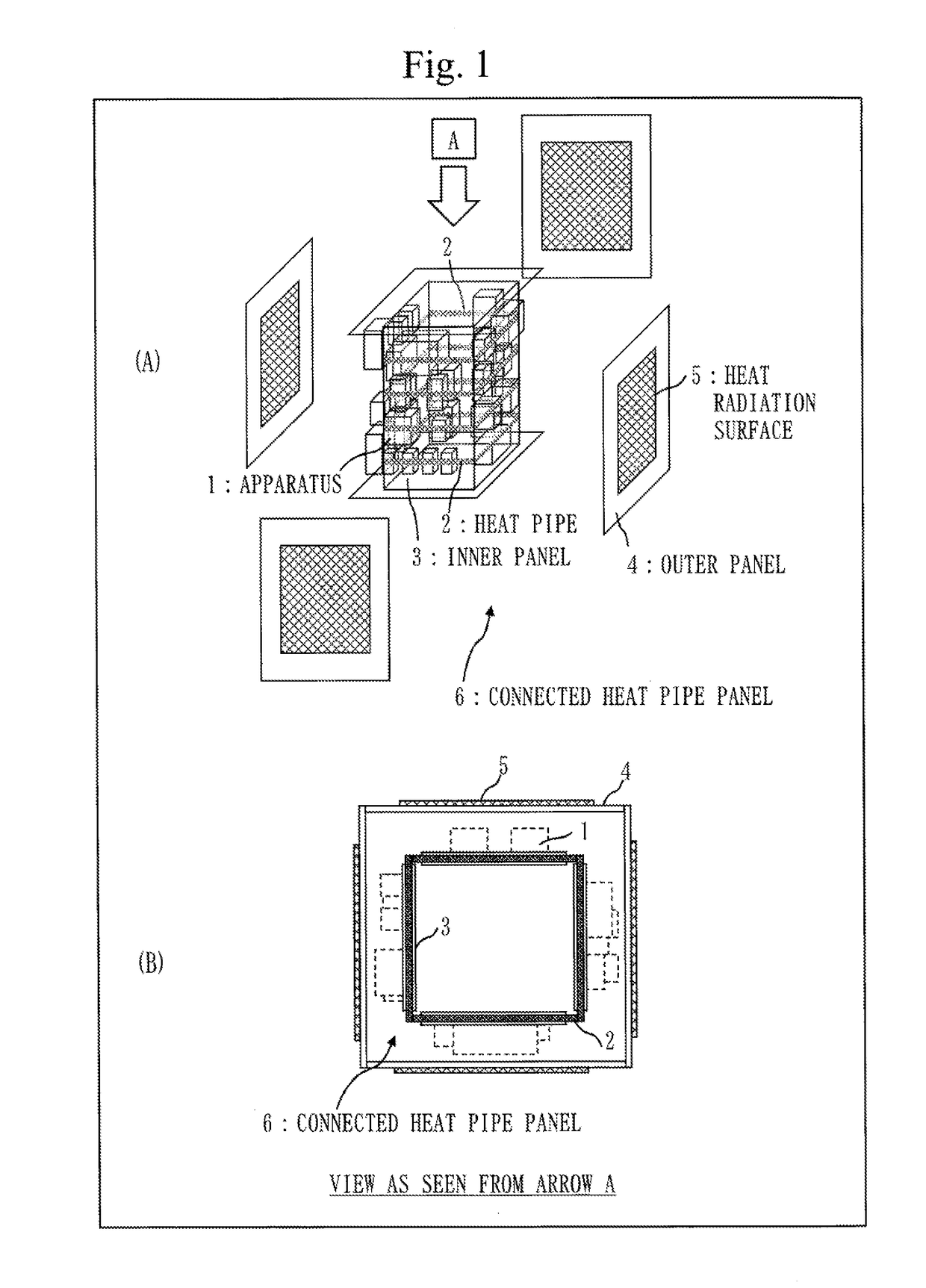
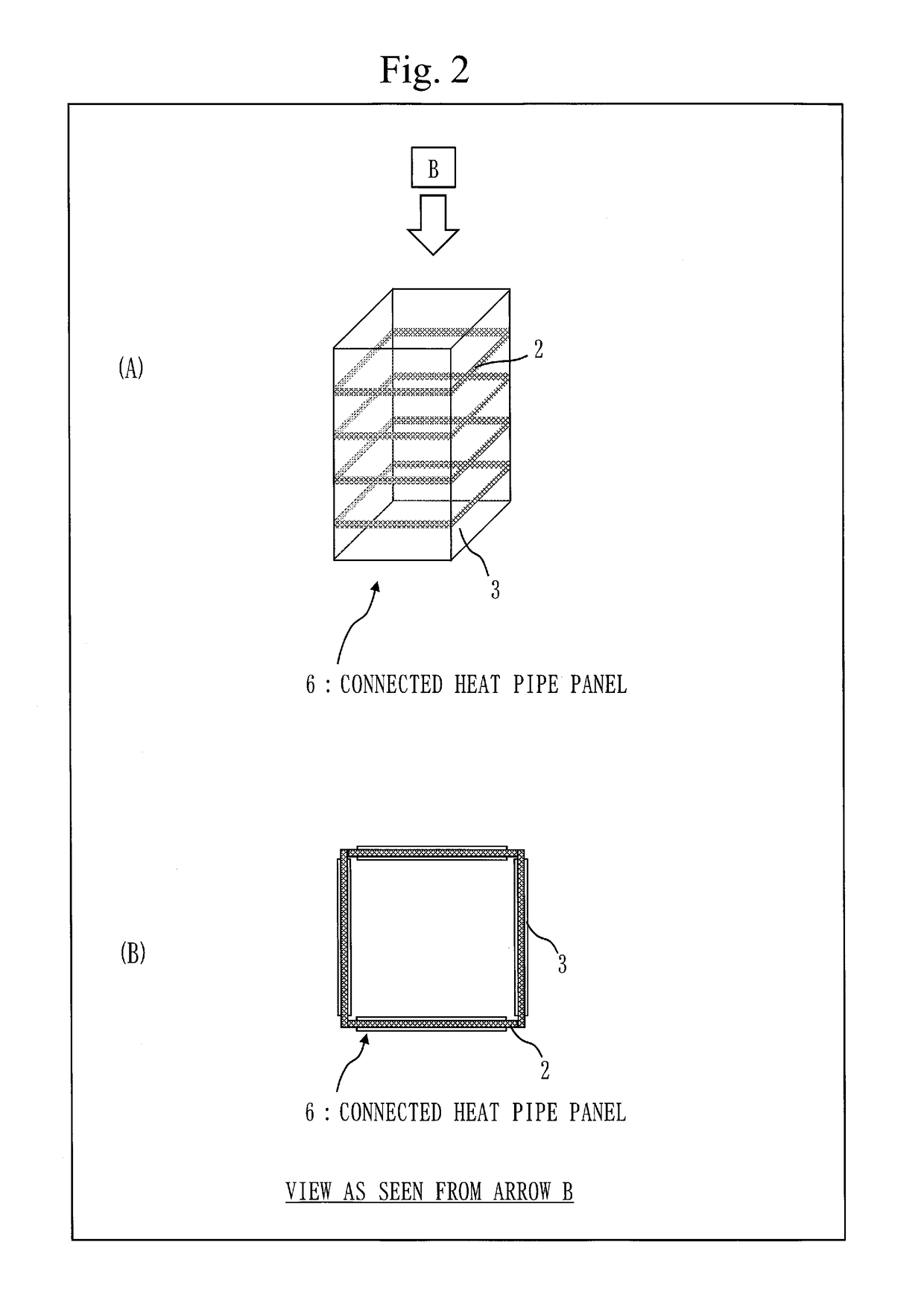
[0067]As a heat radiator according to Embodiment 1, a heat radiator having a hexahedral fuselage shape in which a plurality of heat pipes arranged and built in an orthogonal (horizontal) direction with respect to a direction of a fuselage axis (gravity) are connected in a circumferential direction to be isothermal and heat is radiated to the space from heat radiation surfaces provided on outer panels in a connected heat pipe panel having a structure in which inner panels to which apparatuses are installed have four surfaces in a tubular shape will be explained.

[0068]Though a term of satellite will be used in the following explanation, the term of satellite may be replaced with an artificial satellite or a spacecraft.

[0069]FIG. 1 is a structure view of a heat radiator including a connected heat pipe panel 6 according to Embodiment 1. In FIG. 1, 1 denotes apparatuses such as electronic apparatuses mounted on the satellite, 2 denotes heat pipes built in inner panels 3, 3 denotes the in...

embodiment 2

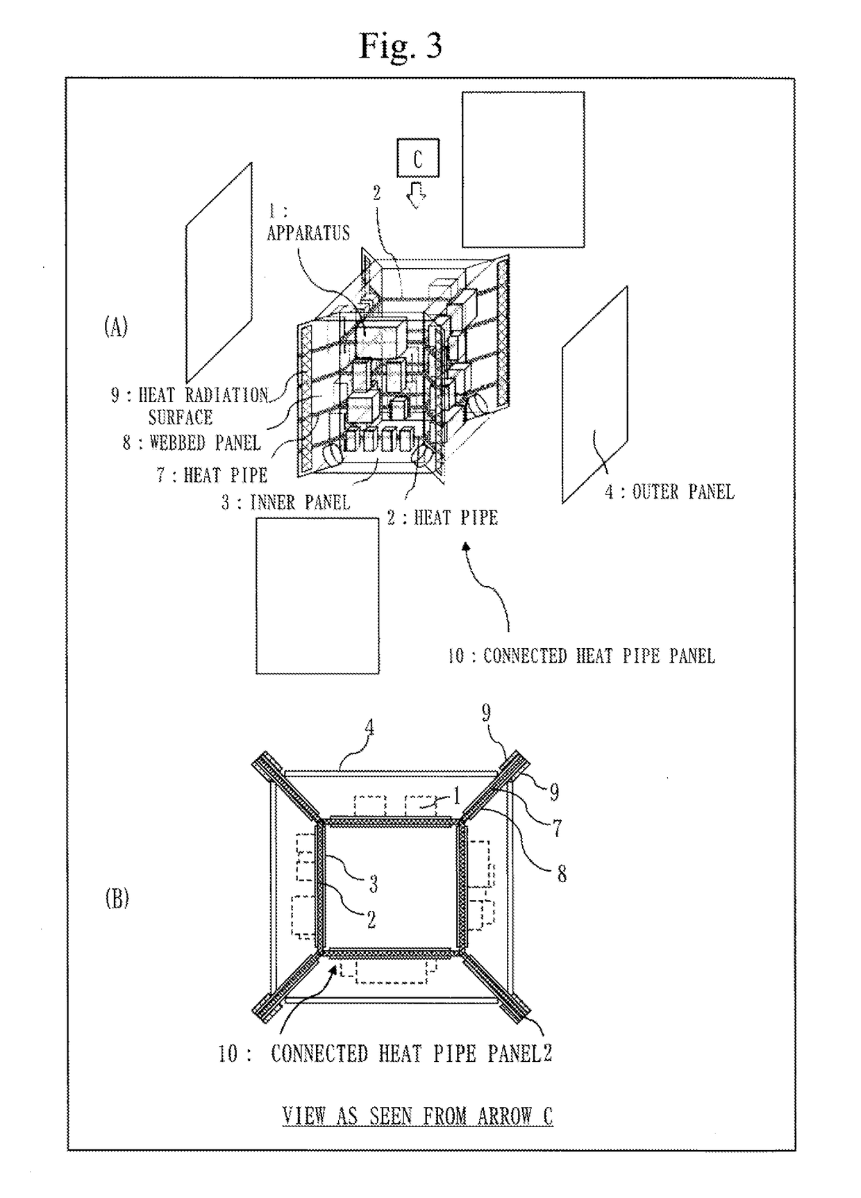
[0081]In Embodiment 2, a heat radiator having a hexahedral fuselage shape in which webbed panels in which heat pipes are built are added with respect to Embodiment 1 and a connected heat pipe panel includes inner panels, webbed panels and heat radiation surfaces provided on the webbed panels will be explained.

[0082]Hereinafter, items different from those in Embodiment 1 will be chiefly explained. Items explanation of which is omitted are the same as those in Embodiment 1.

[0083]FIG. 3 is a structure view of a heat radiator including a connected heat pipe panel 10 according to Embodiment 2. In FIG. 3, 7 denotes heat pipes, 8 denotes webbed panels and 9 denotes heat radiation surfaces.

[0084]FIG. 4 is a structure view of the connected heat pipe panel 10 according to Embodiment 2, in which only the connected heat pipe panel 10 is illustrated from the drawing in FIG. 3.

[0085]The connected heat pipe panel 10 according to Embodiment 2 includes the webbed panels 8 that are radially arranged ...

embodiment 3

[0092]In Embodiment 3, a heat radiator having a hexahedral fuselage shape in which webbed panels and outer panels in which heat pipes are built are added with respect to Embodiment 1 and a connected heat pipe includes inner panels, webbed panels, outer panels and heat radiation surfaces provided on the outer panels will be explained. The embodiment differs from the webbed panel of Embodiment 2 in that the heat radiation surfaces are not provided on the webbed panels in which the heat pipes are built.

[0093]Hereinafter, items different from those in Embodiments 1 and 2 will be chiefly explained. Items explanation of which is omitted are the same as those in Embodiments 1 and 2.

[0094]FIG. 5 is a structure view of a heat radiator including a connected heat pipe panel 14 according to Embodiment 3. In FIG. 5, 12 denotes webbed panels, 11 denotes heat pipes provided in the webbed panels 12 and 13 denotes heat pipes provided in the outer panels 4.

[0095]FIG. 6 is a structure view of the conn...


PUM


Abstract

Inner panels including at least one built-in heat pipe connected in a circumferential direction are provided. In a heat pipe panel including the built-in heat pipe, apparatuses are mounted on the outer side of the plural inner panels connected in the circumferential direction to diffuse generated heat of the apparatuses to the circumferential direction of the inner panels. Webbed panels including a built-in heat pipe horizontally arranged and having heat radiation surfaces are radially arranged at corners of the inner panels as well as a heat pipe is horizontally built in and heat radiation surfaces are arranged also on outer panels facing the inner panels to thermally connect the heat pipes to one another.

Description

TECHNICAL FIELD[0001]In an artificial satellite and a spacecraft, mechanical system design such as thermal structure design and equipment layout design is performed in accordance with apparatuses mounted on the inside and conditions such as an orbit and attitude at the time of putting the satellite or the spacecraft. Therefore, when design conditions differ, the design also differs respectively. The present invention relates to a heat radiator using a connected heat pipe panel in which structure panels in which heat pipes are built are connected in the artificial satellite or the spacecraft, to which the same mechanical system design can be applied even when apparatuses to be mounted or orbit and attitude conditions differ, which can standardize design.BACKGROUND ART[0002]In the artificial satellite and the spacecraft, apparatuses to be mounted and orbit and attitude conditions differ according to respective missions, therefore, thermal structure design and equipment layout design f...

Claims


Application Information

Patent Timeline
Patent Type & Authority Applications(United States)
IPC IPC(8): B64G1/50B64G1/58F28D15/02F28D15/04
CPCB64G1/506B64G1/58F28D15/0241F28D15/043F28D15/0233F28D15/046F28D15/02B64G1/503
Inventor IZU, HIROKIOGURA, YUICHINOMURA, TAKEHIDEHAYASHI, KENGOYAMASHITA, SHINTAROSAKATA, SHIROKITAGAWA, TESTSUYA
Owner MITSUBISHI ELECTRIC CORP
Why Eureka
Try Eureka