Climate management system, and management method and power supply system using same

a technology of management system and power supply system, applied in the field of management system, can solve the problems of prolonged product period, time-consuming and complex task of monitoring, managing and controlling battery units, and shortening the development period of products, extending the use life of dust-proof elements, and reducing the manufacturing cost of products

Inactive Publication Date: 2012-12-06
DELTA ELECTRONICS INC
View PDF5 Cites 2 Cited by
  • Summary
  • Abstract
  • Description
  • Claims
  • Application Information

AI Technical Summary

Benefits of technology

[0009]It is a further object of the present invention to provide a climate management system, and a management method and a power supply system using the same, in which the master climate control unit can collect and combine all the information from the slave climate control units and transmits the integrated information to a control system unit in analog or simple digital signals.
[0010]It is a further object of the present invention to provide a climate management system, and a management method and a power supply system using the same, in which the designer can use various control system unit in the cabinet without editing the programs according to various communication protocols between the control system unit and climate control units so that the developmental periods of the products are shortened and the manufacturing costs of the products are reduced.
[0011]It is a further object of the present invention to provide a climate management system, and a management method and a power supply system using the same, in which a cabinet of the power supply system has a waterproof and dust-reduction mechanism for reducing the dust and providing waterproof function and has an air filter sensor and a climate control unit for discriminating whether the dust-proof element needs to be replaced and issuing a notifying signal to the climate control unit.
[0012]It is a further object of the present invention to provide a climate management system, and a management method and a power supply system using the same to extend the use life of the dust-proof element, provide waterproof function of the cabinet, and reduce the acoustic noise.

Problems solved by technology

When battery units and / or climate devices in the cabinets of the power supply system fail or are out of control, this can cause disruption in related operations.
However, it is a time-consuming and complex task to monitor, manage and control the battery units and climate devices in widely spaced cabinets.
Therefore, the developmental periods of the products are prolonged and the manufacturing costs of the products are increased.
In addition, during operations of the power supply equipments of the power supply system, a great amount of heat is generated.
In a case that the dust-proof element has been used for a prolonged period, the degree of dust accumulation becomes more serious and thus the airflow induced by the fan fails to pass through the dust-proof element.
Under this circumstance, the heat-removing capability of the cabinet is reduced and the performance of the cabinet is deteriorated.
However, how to transmit the notifying signal or information from the climate control units to the control system unit is not easy to be designed.
In addition, it is not easy to extend the use life of the dust-proof element.
Generally, the cabinet may be located outdoors and the cooling airflow introduced into the cabinet may contain relatively great quantity of dust and moisture, which may reduce the use lives of the dust-proof element and the electronic devices inside the cabinet.

Method used


Image

  • Climate management system, and management method and power supply system using same
  • Climate management system, and management method and power supply system using same
  • Climate management system, and management method and power supply system using same

Examples


Embodiment Construction

[0025]The present invention will now be described more specifically with reference to the following embodiments. It is to be noted that the following descriptions of preferred embodiments of this invention are presented herein for purpose of illustration and description only. It is not intended to be exhaustive or to be limited to the precise form disclosed.

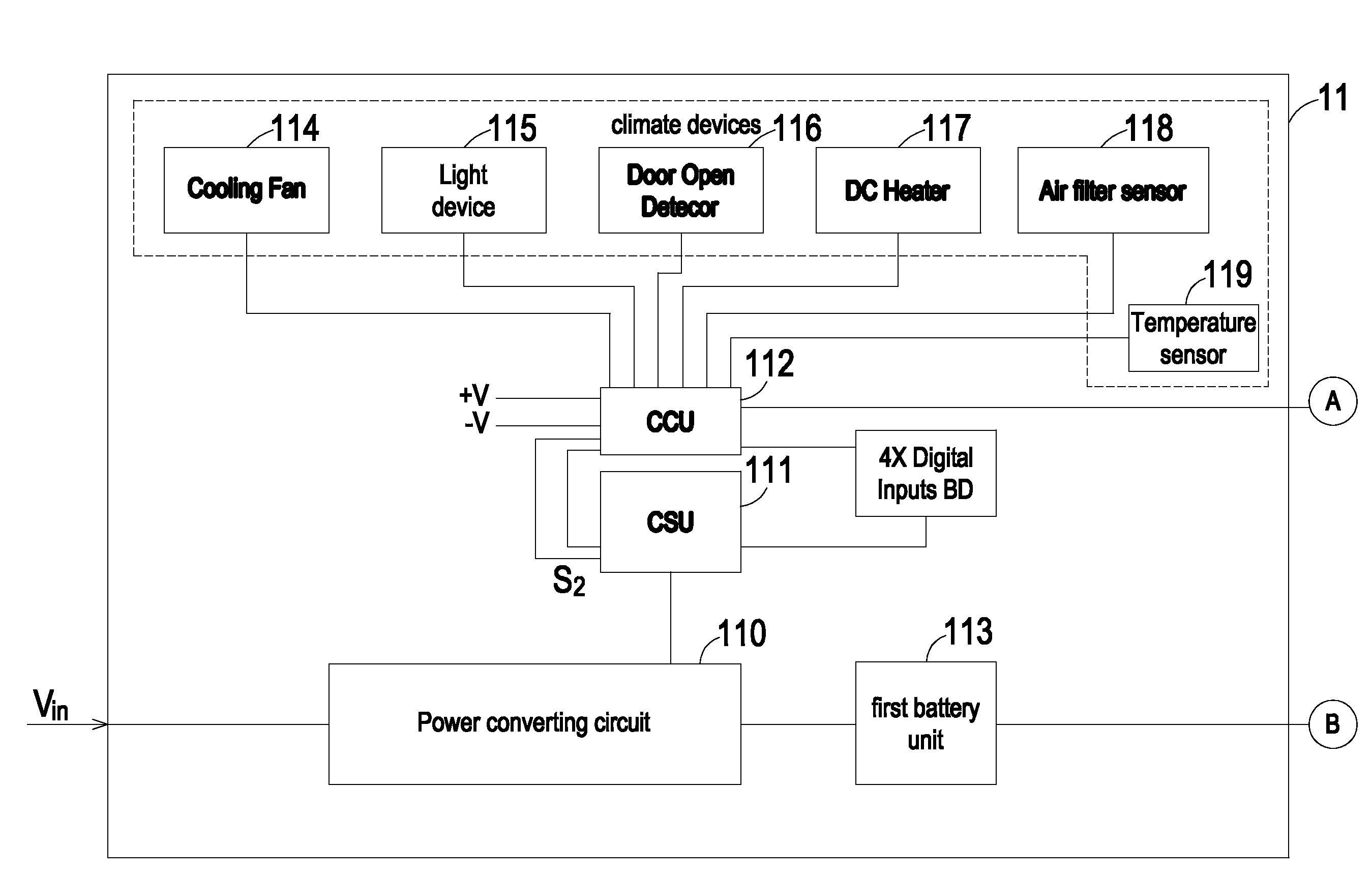
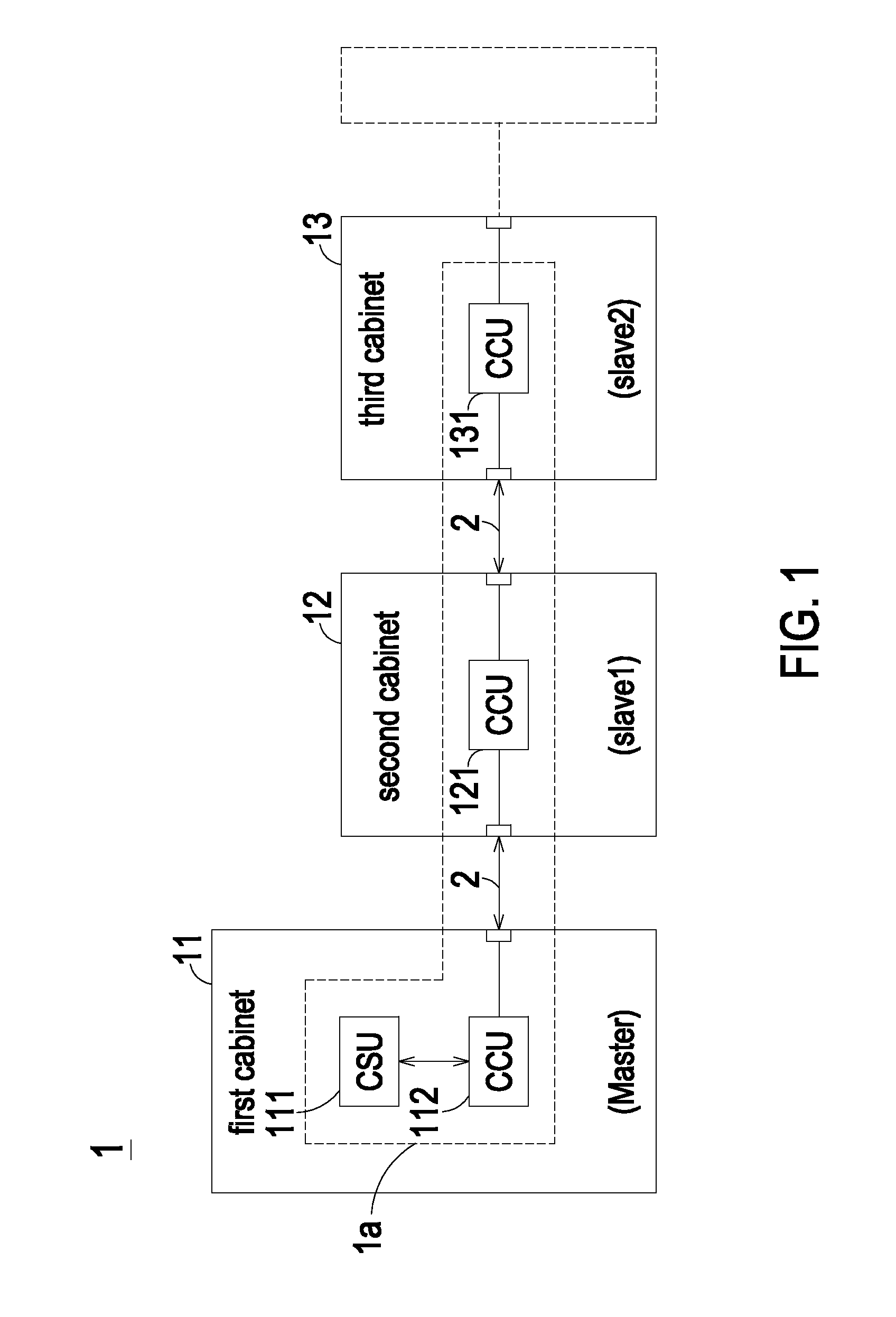
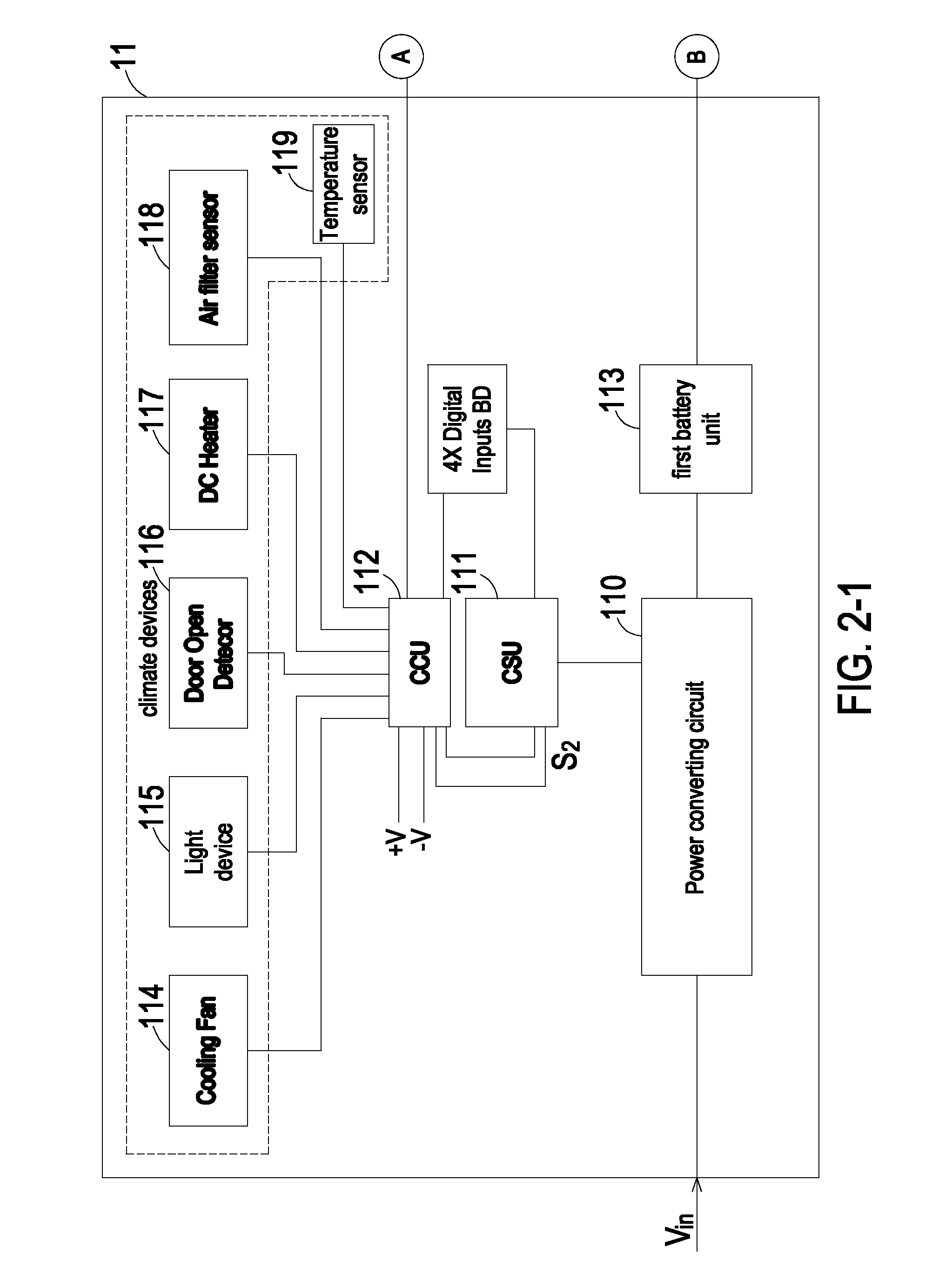
[0026]FIG. 1 is a block diagram showing a climate management system for a power supply system according to the preferred embodiment of the present invention; and FIG. 2 is a circuit diagram of the power supply system of FIG. 1. As shown in FIGS. 1 and 2, the power supply system 1 includes a plurality of cabinets, which are connected in series and may be spaced many meters apart with each other. In an embodiment, the power supply system 1 is a telecommunication power supply system, but it is not limited thereto. In an embodiment, the power supply system 1 includes three cabinets for example a first cabinet 11, a second cabinet 12 ...


PUM


Abstract

A climate management system for a power supply system including a plurality of cabinets is disclosed. The climate management system comprises a plurality of climate control units connected and in communication with each other, wherein each climate control unit is disposed in a corresponding cabinet to monitor, manage and control the corresponding cabinet, wherein one of the climate control units is defined as a master climate control unit and the other of the climate control units are defined as slave climate control units; and a control system unit connected and in communication with the master climate control unit. The master climate control unit is configured to collect, process and integrate the information transmitted from the slave climate control units and report the collected, processed and integrated information to the control system unit.

Description

CROSS-REFERENCE TO RELATED APPLICATION[0001]This application claims the benefit of U.S. Provisional Application No. 61 / 493,084 filed on Jun. 3, 2011, and entitled “CLIMATE MANAGEMENT SYSTEM AND METHOD FOR POWER SUPPLY SYSTEM”, the entirety of which is hereby incorporated by reference.FIELD OF THE INVENTION[0002]The present invention relates to a management system, and more particularly to a climate management system, and a management method and a power supply system using the same.BACKGROUND OF THE INVENTION[0003]With increasing development of information industries and communication networks, the services provided through communication networks are becoming more and more popular in various applications. Telecommunication systems are essential electronic equipments for use in the communication networks and include a variety of hardware and software components that may be configured to process, store, communicate and exchange information. For providing required and uninterrupted powe...

Claims


Application Information

Patent Timeline
Patent Type & Authority Applications(United States)
IPC IPC(8): H05K7/20G05D23/19
CPCH05K7/20572G05D23/1934H05K7/207
Inventor HSU, YAO-FENGHUANG, TA-YUWANG, PO-CHINGJIANG, MAO-HSUAN
Owner DELTA ELECTRONICS INC
Why Eureka
Try Eureka