
Pilot signal power control apparatus and operation method of pilot signal power control apparatus

a technology of power control apparatus and pilot signal, which is applied in the direction of power management, electrical equipment, transmission monitoring, etc., can solve the problems of low power of data signal of primary network, inability of primary network to increase channel capacity, and may not recognize that primary network is using the available frequency resources. to achieve the effect of maximizing channel capacity

Active Publication Date: 2012-01-17
SAMSUNG ELECTRONICS CO LTD +1
View PDF7 Cites 5 Cited by
  • Summary
  • Abstract
  • Description
  • Claims
  • Application Information

AI Technical Summary

Benefits of technology

[0008]Aspects of the present invention provide a pilot signal power control apparatus and operation method thereof that estimates a noise increase occurring due to a channel estimation error, measures a channel capacity, determines a power level of a pilot signal using the calculated channel capacity, and thereby allocates a transmission power to the pilot signal in order to maximize the channel capacity.
[0010]Aspects of the present invention also provide a pilot signal power control apparatus and operation method thereof that calculates a channel capacity according to a modulation coding scheme (MCS), determines an optimal power of the pilot signal based on the calculated channel capacity, and thereby improves a data transmission rate.

Problems solved by technology

When power of the pilot signal is low, the secondary network may not recognize that the primary network is using the available frequency resources.
Conversely, when the power of pilot signal is high, power of the data signal of the primary network may be low as a result.
Moreover, when the power of the data signal of the primary network is insignificant or low, the primary network cannot increase a channel capacity.

Method used


Image

  • Pilot signal power control apparatus and operation method of pilot signal power control apparatus
  • Pilot signal power control apparatus and operation method of pilot signal power control apparatus
  • Pilot signal power control apparatus and operation method of pilot signal power control apparatus

Examples


Embodiment Construction

[0020]Reference will now be made in detail to the present embodiments of the present invention, examples of which are illustrated in the accompanying drawings, wherein like reference numerals refer to the like elements throughout. The embodiments are described below in order to explain the present invention by referring to the figures.

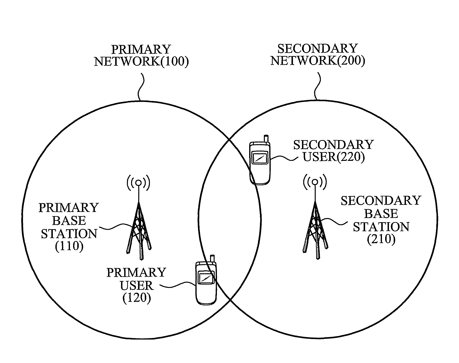
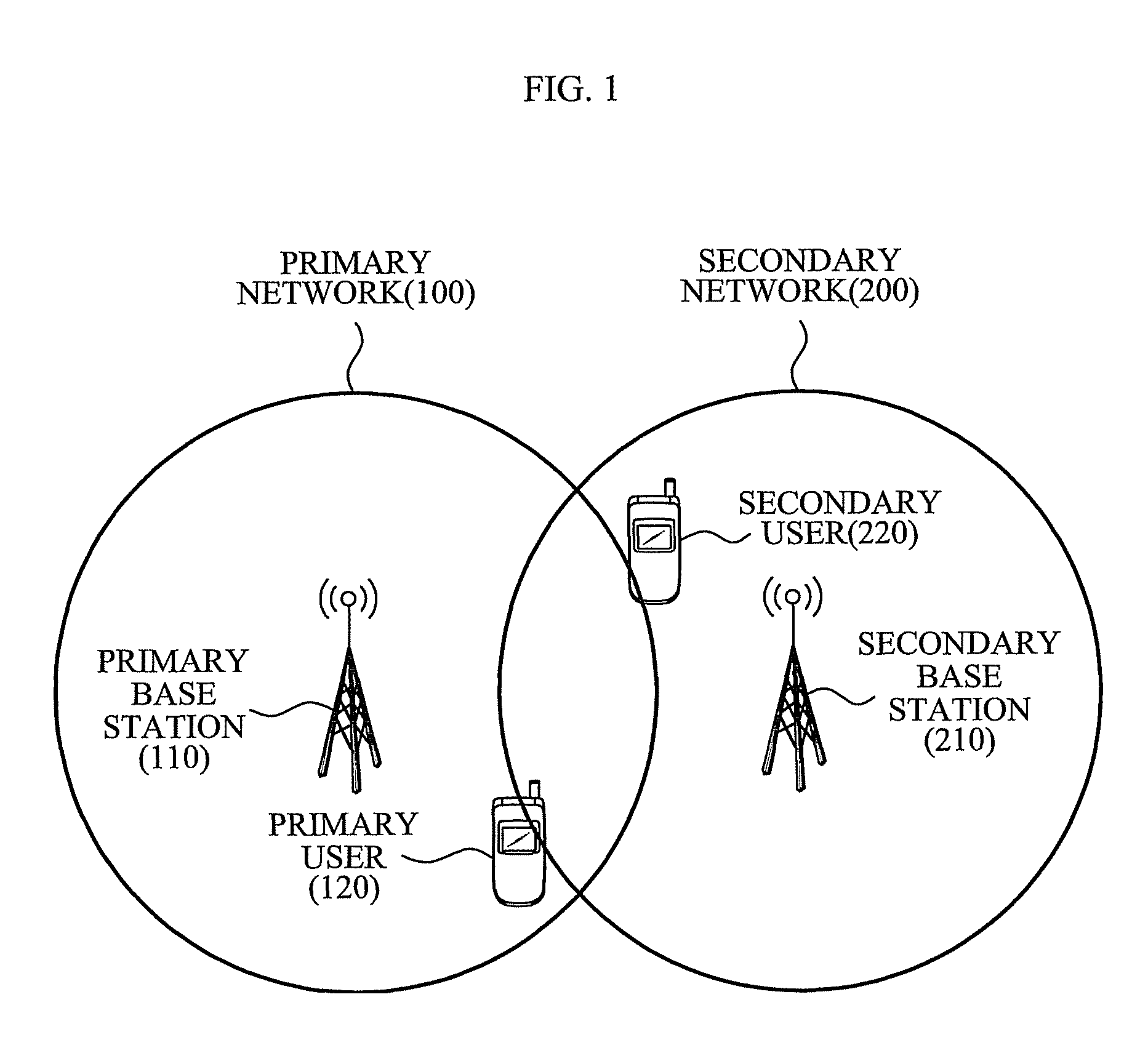
[0021]FIG. 1 illustrates a primary network 100 and a secondary network 200 according to an embodiment of the present invention. Referring to FIG. 1, the primary network 100 includes a primary base station 110 and a primary user 120, and the secondary network includes a secondary base station 210 and a secondary user 220.

[0022]The primary network 100 uses a frequency resource allocated to the primary network 100 without considering whether the secondary base station 210 or the secondary terminal 220 receives and / or transmits a signal on the frequency resource. In this instance, the secondary base station 210 and / or the secondary terminal 220 may recogni...


PUM


Abstract

A pilot signal power control apparatus to determine a power level of a pilot signal of a primary network to indicate an availability of a wireless resource of thereof to a secondary user of a secondary network according to a cognitive radio technology, the pilot signal power control apparatus and an operation method thereof, the pilot signal power control apparatus including: a prediction unit to predict a noise increase and / or a sensing probability, the noise increase occurring in a primary user of the primary network due to a channel estimation error, and the sensing probability being a probability that a secondary user senses the pilot signal of; a channel capacity calculation unit to calculate a channel capacity of the primary user based on the predicted noise increase and / or sensing probability; and a power level determination unit to determine the power level of the pilot signal using the calculated channel capacity.

Description

CROSS-REFERENCE TO RELATED APPLICATION[0001]This application claims the benefit of Korean Application No. 2007-114996, filed Nov. 12, 2007, in the Korean Intellectual Property Office, the disclosure of which is incorporated herein by reference.BACKGROUND OF THE INVENTION[0002]1. Field of the Invention[0003]Aspects of the present invention relate to a cognitive radio technology, and more particularly, to a technology to control a pilot signal power.[0004]2. Description of the Related Art[0005]Currently, much research on technologies to efficiently use limited frequency resources has been conducted. Among these technologies, a cognitive radio (CR) technology reuses frequency resources to efficiently use the limited frequency resources. That is, according to the CR technology, a communication apparatus in a secondary network periodically or irregularly senses frequency resources that are not used in a primary network to recognize available frequency resources. Accordingly, the communic...

Claims


Application Information

Patent Timeline
Patent Type & Authority Patents(United States)
IPC IPC(8): H04B1/00H04B15/00H04B17/00
CPCH04W52/223H04W52/325H04B17/336H04W52/244
Inventor KWON, TAE SOOLEE, IN SUNHWANG, HYO SUNKIM, YOUNGSOOCHOI, HYUN HOLEE, YOUNG HOONSUNG, YOUNG CHULYU, HEE JUNGOH, YOUNG SEOK
Owner SAMSUNG ELECTRONICS CO LTD
Learn More