
Washer for hinge assembly

a technology for hinge assemblies and washers, applied in the field of washers, can solve the problems of reducing mechanical efficiency and large friction torque produced by e-shape washers

Inactive Publication Date: 2012-01-24
SHENZHEN FUTAIHONG PRECISION IND CO LTD +1
View PDF9 Cites 8 Cited by
  • Summary
  • Abstract
  • Description
  • Claims
  • Application Information

AI Technical Summary

Benefits of technology

The C-shape washer improves mechanical efficiency and stability by minimizing friction and abrasion, ensuring smoother operation and extended lifespan of the hinge assembly.

Problems solved by technology

However, when the sleeve rotates relative to the shaft, a large friction torque is produced between the E-shape washer and the sleeve.
This will reduce mechanical efficiency.

Method used


Image

  • Washer for hinge assembly
  • Washer for hinge assembly
  • Washer for hinge assembly

Examples


Embodiment Construction

[0013]The present washer is suitable for a hinge assembly for foldable electronic device such as a foldable mobile phone. It is to be understood, however, that the hinge assembly could be advantageously used in other environments (e.g. cabinet doors).

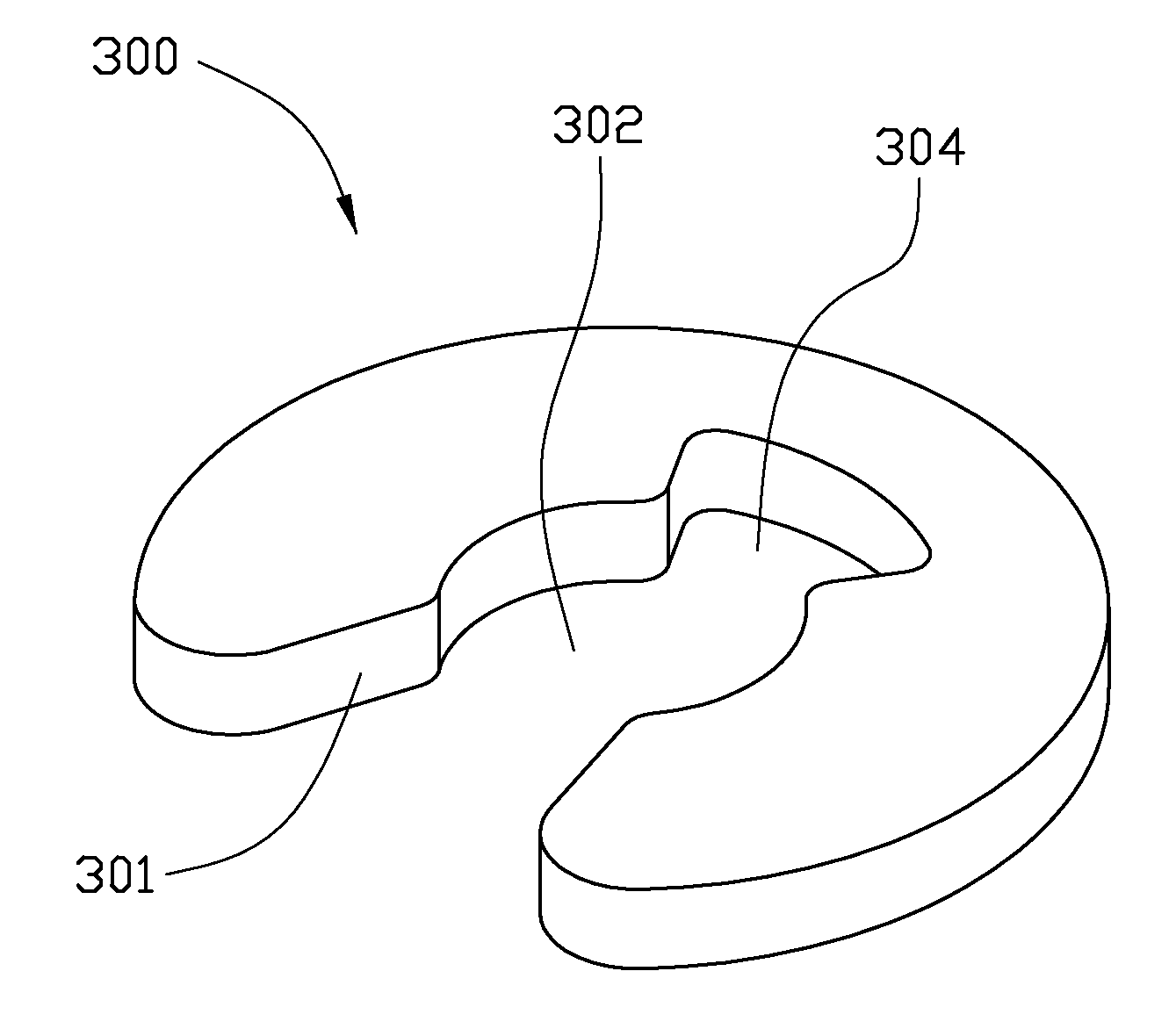
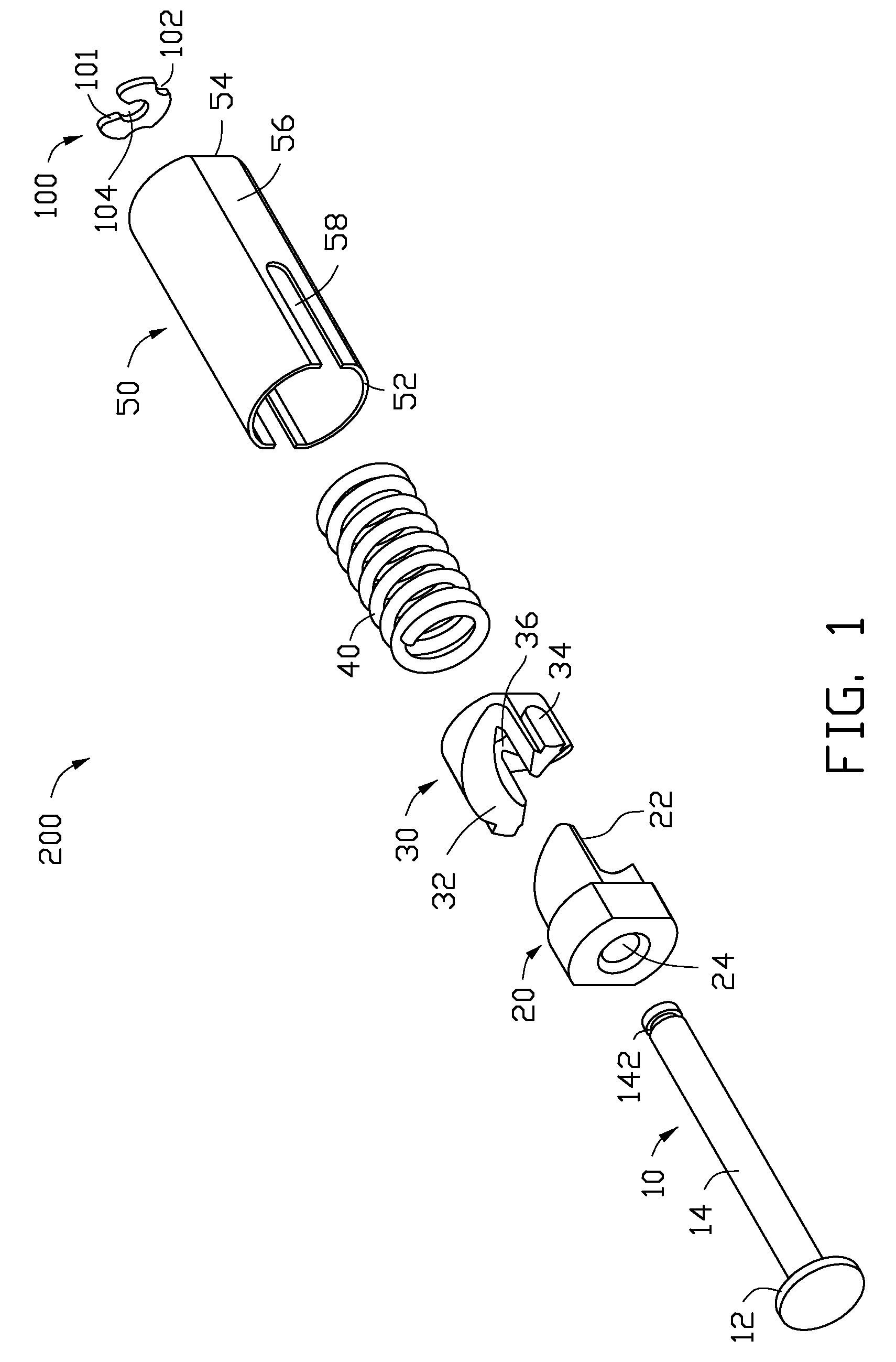
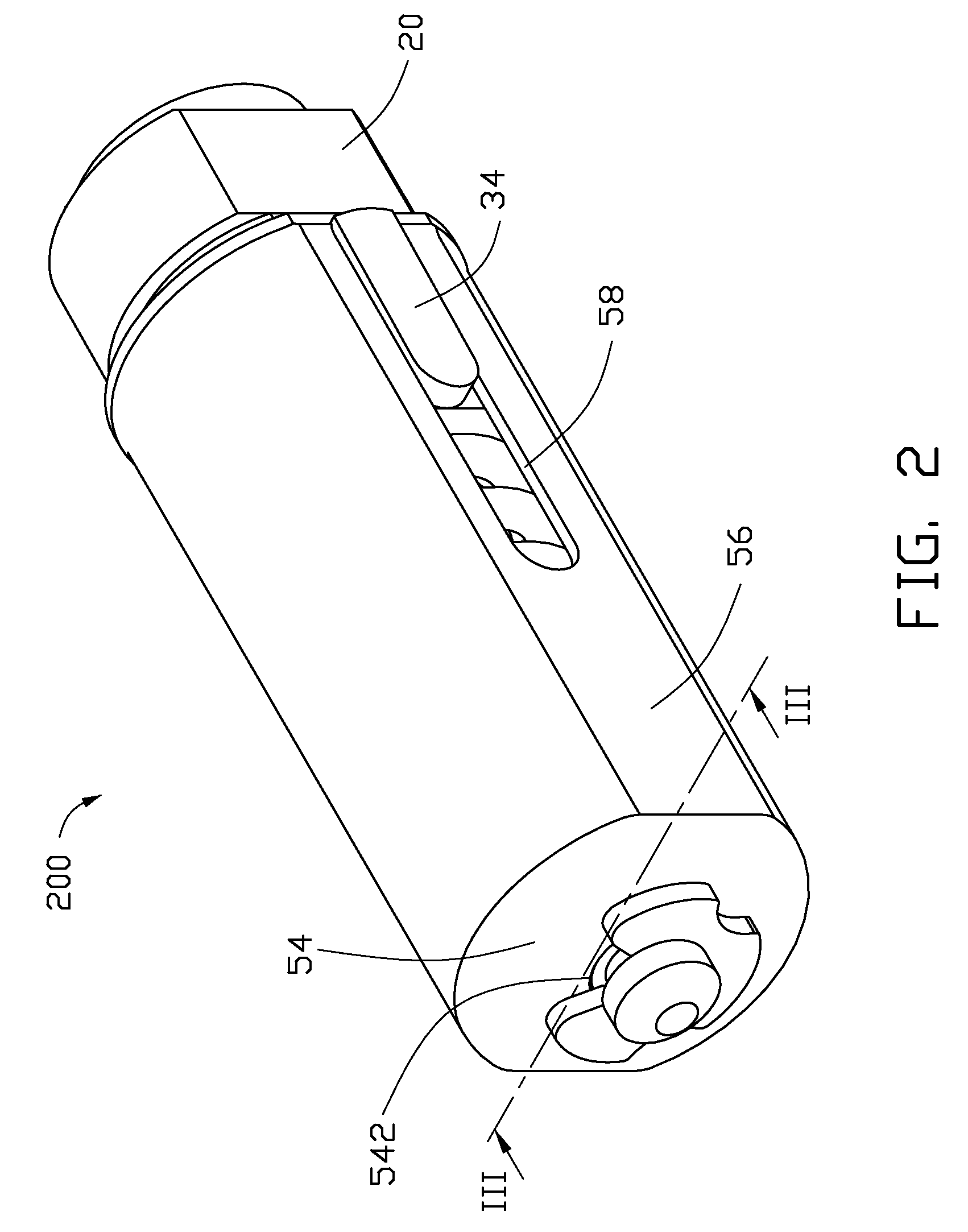
[0014]Referring to FIGS. 1 and 2, an exemplary hinge assembly 200 includes a main shaft 10, a follower 20, a rotary element 30, an elastic element 40, a sleeve 50, and a washer 100.

[0015]The main shaft 10 coaxially includes a flange portion 12 and a shaft portion 14. The flange portion 12 is formed at an end of the main shaft 10. The shaft portion 14 extends from a side of the flange portion 12. A diameter of the shaft portion 14 is smaller than the diameter of the flange portion 12. A free end of the shaft portion 14 defines a ring groove 142.

[0016]The follower 20 is for connecting with a body section (not shown). The follower 20 forms a cam surface22 at one end thereof. The follower 20 defines a passage 24 for receiving the shaft port...


PUM


Abstract

A washer is for a hinge assembly. The hinge assembly includes a shaft. The washer is placed around the shaft. The engagement between the washer and the shaft is a clearance fit. By the clearance engagement between the washer and the main shaft, the mechanism efficiency is greatly improved.

Description

BACKGROUND[0001]1. Technical Field[0002]The present disclosure relates to washers, and particularly to washers for hinge assemblies for foldable electronic devices, such as mobile phones and portable computers.[0003]2. Description of Related Art[0004]Presently, perhaps the most popular portable electronic device in the marketplace is the foldable mobile phone, which generally includes a cover section and a body section. The cover section and the body section are rotatably interconnected through a hinge assembly, for switching the mobile phone between an in-use position and a closed position.[0005]A typical hinge assembly used in small foldable electronic devices includes a shaft, a cam, a follower, a spring, a sleeve and an E-shape washer. The sleeve has a partially-closed end and an open end. The cam and the spring are placed on the shaft, and are received in the sleeve. The E-shape washer is locked at one end of the shaft, and resists the outside of the partially-closed end of the...

Claims


Application Information

Patent Timeline
Patent Type & Authority Patents(United States)
IPC IPC(8): E05D11/08
CPCF16B21/186G06F1/1681E05D5/128E05Y2800/412Y10T16/557E05Y2900/606Y10T16/54038Y10T16/5403E05Y2999/00
Inventor DUAN, CHAOCHEN, CHIA-HUAHU, ZHI-YU
Owner SHENZHEN FUTAIHONG PRECISION IND CO LTD
Learn More