Cyclone separating device of a cleaner

a technology of separating device and cleaner, which is applied in the field of devices, can solve the problems of increasing production cost, increasing the number of components, and causing new problems, and causing great trouble for the device operator

Active Publication Date: 2012-01-24
ECOVACS ROBOTICS (SUZHOU ) CO LTD
View PDF23 Cites 84 Cited by
  • Summary
  • Abstract
  • Description
  • Claims
  • Application Information

AI Technical Summary

Benefits of technology

[0018]With the height of the present invention being the sum of the height of the upstream separating device plus the height of the recumbent downstream separating device, the cyclone separating device is not only smaller in radial dimension but also lower in height.

Problems solved by technology

However, an obvious disadvantage of the known art mentioned above is its bulky size, which causes great trouble to the device operator.
Besides, the long gas passageway between the two cyclone separating devices results in a complicated manufacturing process, which means more components and a higher production cost.
However, new problems come up.
Such designed device lowers its height to some extent, but is still large in radial direction, and thus finds no application in many cases.

Method used


Image

  • Cyclone separating device of a cleaner
  • Cyclone separating device of a cleaner
  • Cyclone separating device of a cleaner

Examples


first embodiment

The First Embodiment

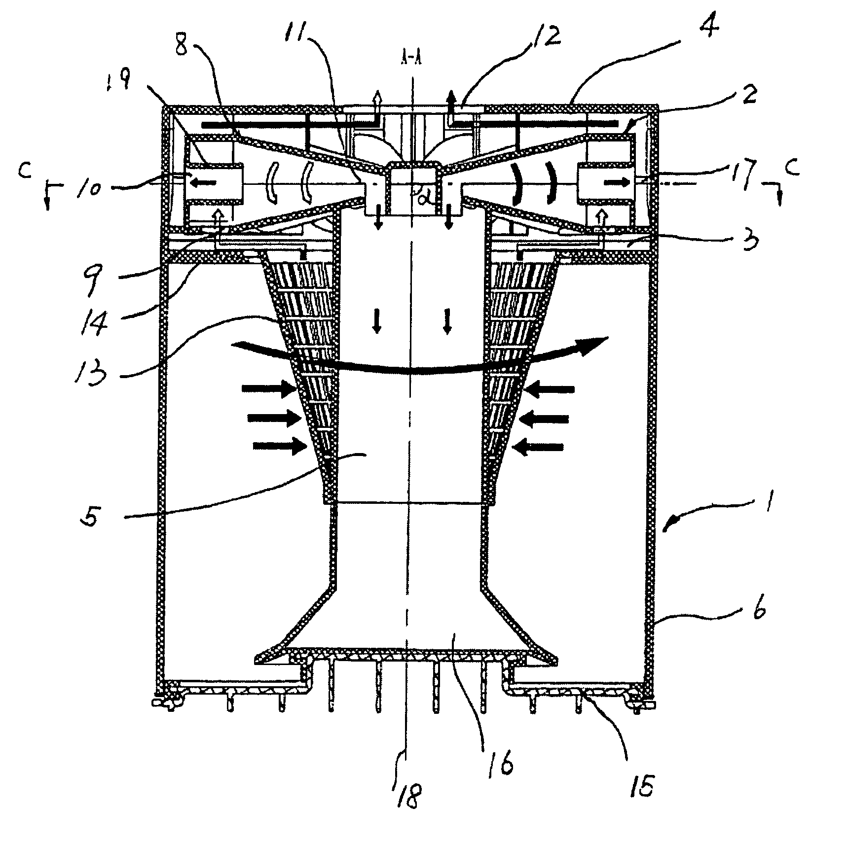
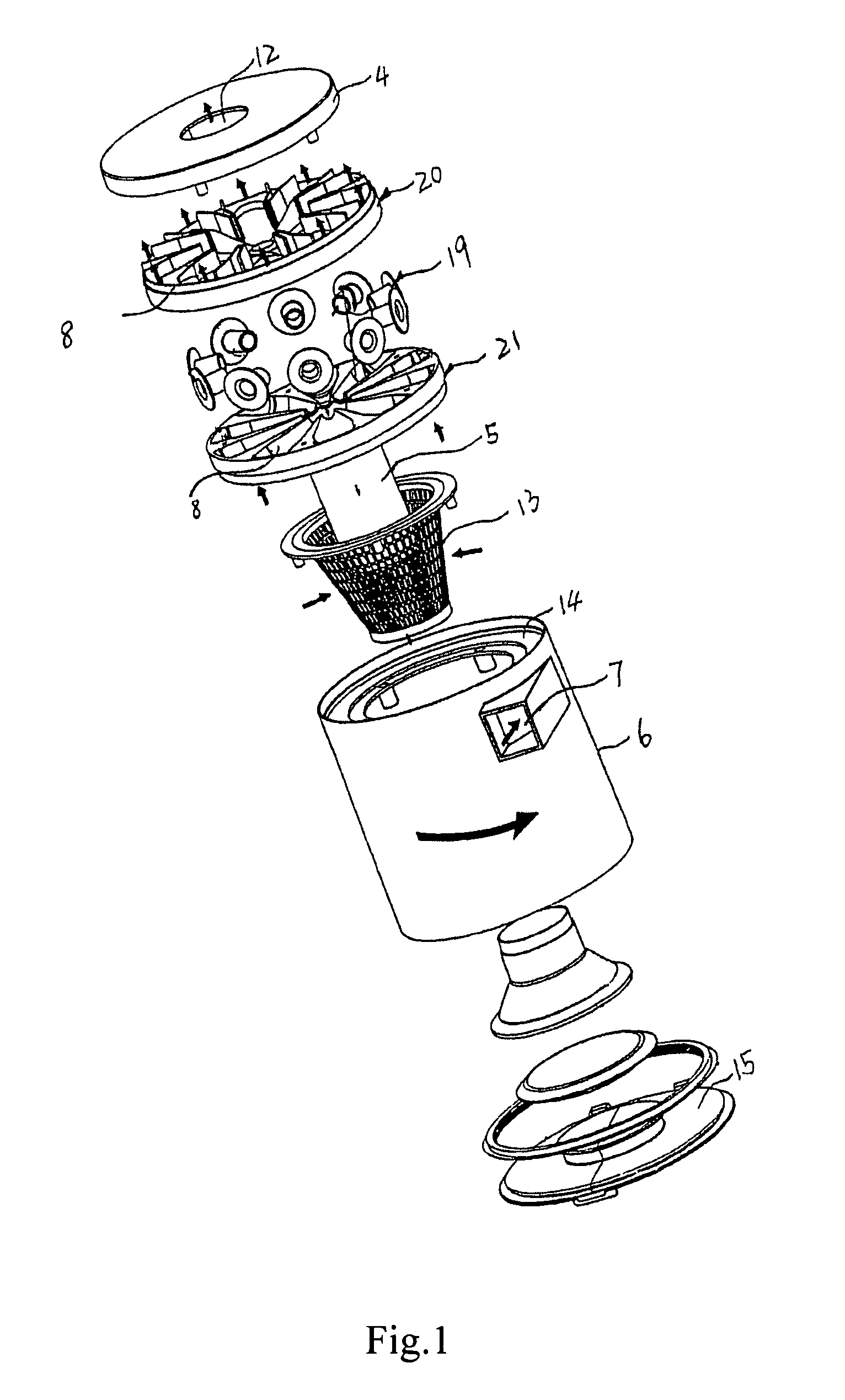
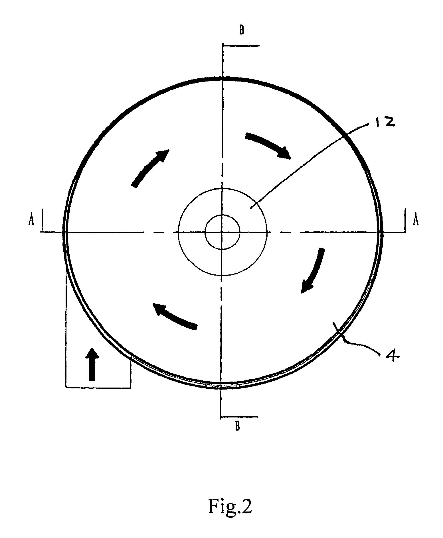
[0067]With reference to FIG. 1 to FIG. 5, the cyclone separating device according to this embodiment includes an upstream cyclone separating device 1, a downstream cyclone separating device 2 and a gas passage 3 therebetween connecting the upstream cyclone separating device 1 and the downstream cyclone separating device 2 so that they are communicated with each other.

[0068]The upstream cyclone separating device 1 has a first cyclone barrel 6 and the down cyclone separating device 2 has ten second cyclone barrels 8 with several of second cyclones 8′ coordinately set. The whole downstream cyclone separating device 2 sleeps above the upstream cyclone separating device 1 recumbently. The axis 17 of the second cyclone barrel 8 is cornered with the axis 18 of the first cyclone 6 to form an angle α. The downstream cyclone separating device 2 is substantially lying down when the angle is in the range from 75 to 125 degree.

[0069]The angle α is 90 degree in the present emb...

second embodiment

The Second Embodiment

[0075]With reference to FIG. 6 and FIG. 7, the cyclone separating device according to this embodiment includes an upstream cyclone separating device 1′ having a first cyclone barrel 6′, a downstream cyclone separating device 2′ having eight second cyclone barrels 8′, and a gas passage 3′ therebetween connecting the upstream cyclone separating device 1′ and the downstream cyclone separating device 2′ so that the two can communicate with each other. The downstream cyclone separating device 2′ sleeps above the upstream cyclone separating device 1′ in a half-lying manner, to be more specific, the downstream cyclone separating device 2′ is half-lying while the angle α between the axis 17′ of the second cyclone barrel 8′ and the axis 18′ of the first cyclone barrel 6′ ranges from 15 to 165 degree.

[0076]The angle α is 135 degree here in this embodiment. The sidewall of the first cyclone barrel 6′ is formed with a first suction mouth 7′ through which the dust laden gas ...


PUM

PropertyMeasurementUnit
angleaaaaaaaaaa
spatial angleaaaaaaaaaa
angleaaaaaaaaaa

Abstract

A cyclone separating device of a cleaner includes an upstream cyclone separating device and a downstream cyclone separating device. The upstream separating device communicates with the downstream cyclone separating device through a gas passage. The upstream cyclone separating device has a first cyclone barrel, while the downstream cyclone separating device has at least one second cyclone barrel. The downstream cyclone separating device is lying and set above the upstream separating device. The size of the cyclone separating device of the present invention is small in radial direction. The height of the cyclone separating device which is the sum of the height of the upstream cyclone separating device plus the height of the lying downstream cyclone separating device lying down is low.

Description

FIELD OF THE INVENTION[0001]The present invention relates to a device for extracting solid from fluid body, and particularly to a cyclone separating device of a cleaner for separating dust and other dirt from airflow.BACKGROUND OF THE INVENTION[0002]Cyclone separating devices can be used to separate dust and other dirt from airflow by virtue of the centrifugal force produced by a highly revolving flow in the cyclone barrel. In the prior art, two-leveled cyclone separating devices are adopted in a serial, so that big sized dust can be extracted from the dust laden air firstly through an upstream separating device, then small dust particles are eliminated through a downstream separating device, which finally attains the purpose of purifying the air.[0003]However, an obvious disadvantage of the known art mentioned above is its bulky size, which causes great trouble to the device operator. Besides, the long gas passageway between the two cyclone separating devices results in a complicat...

Claims


Application Information

Patent Timeline
Patent Type & Authority Patents(United States)
IPC IPC(8): B01D45/00
CPCA47L9/1625A47L9/1641A47L9/1666A47L9/1683B04C5/13B04C5/187B04C5/26B04C5/28B04C2009/004
Inventor QIAN, DONGQI
Owner ECOVACS ROBOTICS (SUZHOU ) CO LTD
Why Eureka
Try Eureka