
Method and apparatus for estimating induction motor electrical parameters

a technology of induction motor and electrical parameters, which is applied in the direction of motor/generator/converter stopper, dynamo-electric converter control, instruments, etc., can solve the problems of requiring interruption of normal motor operation, difficult, if not impossible, to apply these tests to motors that have already been installed, and it is not practical to implement this approach for line-connected motors. , to achieve the effect of adding cost and bulk to the motor

Active Publication Date: 2012-01-24
SCHNEIDER ELECTRIC USA INC
View PDF27 Cites 21 Cited by
  • Summary
  • Abstract
  • Description
  • Claims
  • Application Information

AI Technical Summary

Benefits of technology

The patent describes a method and device for estimating the electrical parameters of an induction motor. This is done by analyzing data from the motor's nameplate and measuring voltage and current at different locations in the motor. The method does not require any additional sensors or injection circuits. It involves synthesizing voltage and current space vectors, detecting the rotor's speed, and obtaining the positive sequence of the motor's fundamental frequency. These parameters can then be used to determine the motor's electrical properties using a dynamic model. The technical effect of this invention is to provide a more accurate and efficient way to estimate the electrical parameters of induction motors.

Problems solved by technology

Such tests require interruption of normal motor operation.
Therefore, it is often difficult, if not impossible, to apply these tests to motors that have already been installed.
Although reasonably accurate estimates of induction motor electrical parameters are usually obtainable using this approach, in practice, it is rather impractical to implement this approach for line-connected motors because separate electronic circuits are required to modify the stator voltage waveforms.
However, while certain schemes in this approach are based on the steady-state induction motor equivalent circuit model, others still require spectrally rich excitation signals be injected into the motor.
It is possible that they do not work well for line-connected motors under dynamic motor operations, such as the applications where motors are connected to time-varying loads of reciprocating compressors or pumps.
However, because of the cost and fragile nature of such a speed sensor, and because of the difficulty of installing the sensor in many motor applications, speed-sensorless schemes based on induction motor magnetic saliency are preferred.

Method used


Image

  • Method and apparatus for estimating induction motor electrical parameters
  • Method and apparatus for estimating induction motor electrical parameters
  • Method and apparatus for estimating induction motor electrical parameters

Examples


Embodiment Construction

[0039]Although the invention will be described in connection with certain aspects and / or embodiments, it will be understood that the invention is not limited to those particular aspects and / or embodiments. On the contrary, the invention is intended to cover all alternatives, modifications, and equivalent arrangements as may be included within the spirit and scope of the invention as defined by the appended claims.

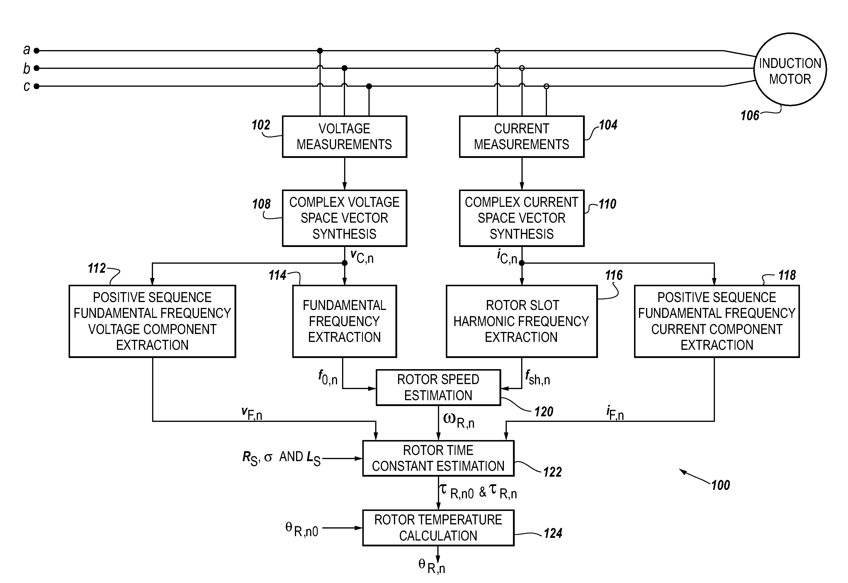
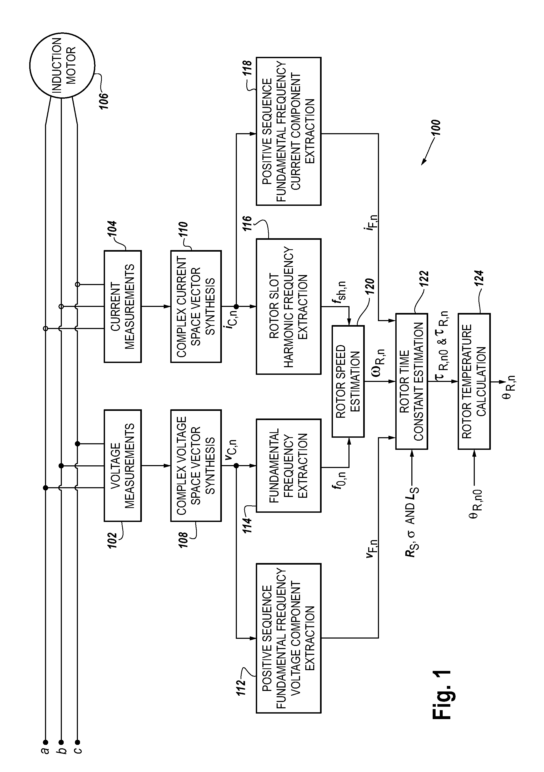
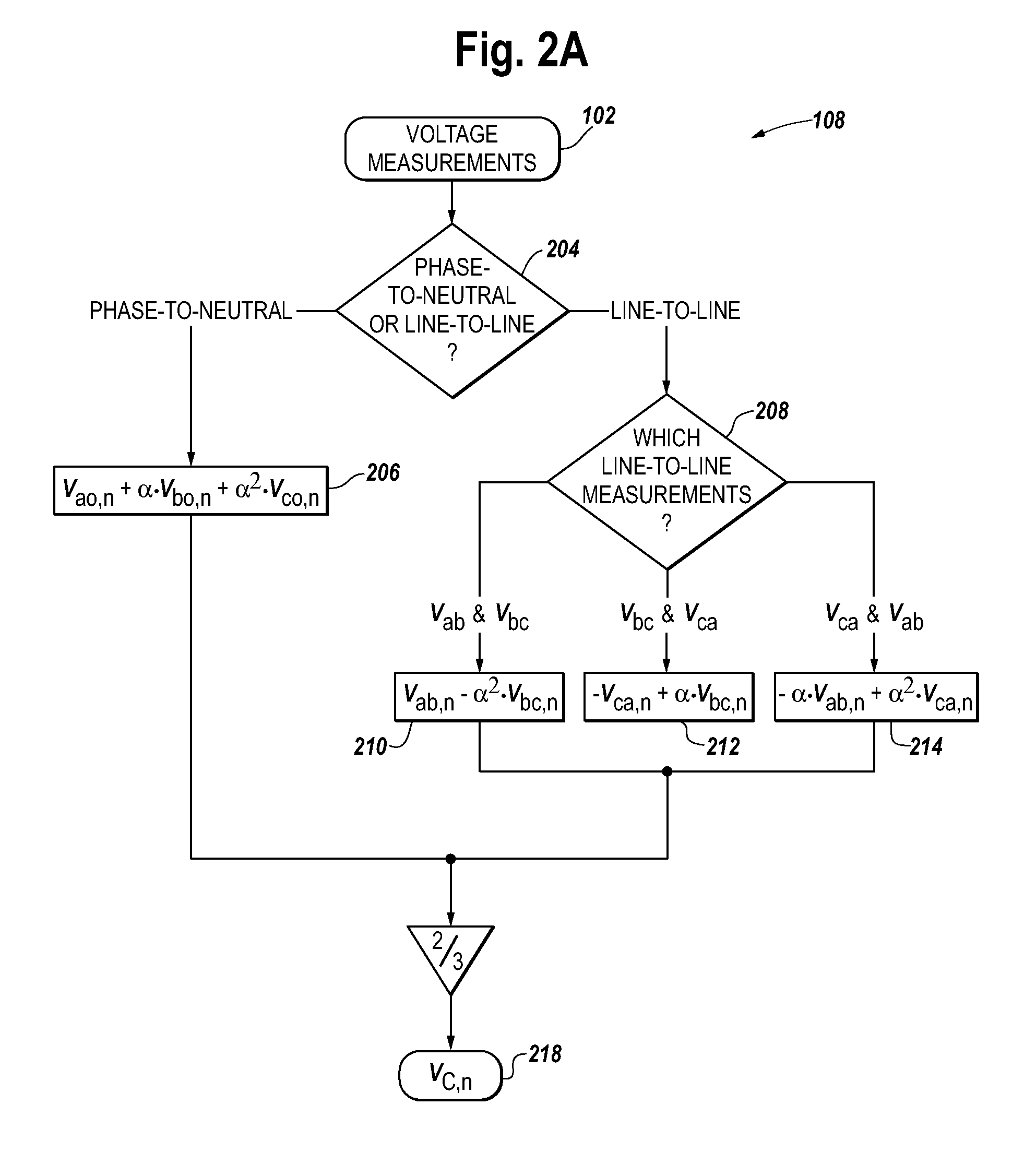
[0040]Referring to FIG. 1, an architecture (100) for estimating rotor temperature in an induction motor 106 is illustrated according to some aspects of the present concepts. The architecture (100) includes a complex voltage space vector synthesis (108), a complex current space vector synthesis (110), a rotor speed estimation (120), a positive sequence fundamental frequency voltage component extraction (112), a positive sequence fundamental frequency current component extraction (118), a rotor time constant estimation (122), and a rotor temperature calculation (124).

Complex ...


PUM


Abstract

A method and apparatus to provide estimates of electrical parameters for line-connected induction motors during either steady-state or dynamic motor operations. The electrical parameters are calculated from the motor nameplate data and voltage and current measurements. No speed sensors or electronic injection circuits are needed. The method can be divided into 4 major steps. First, complex space vectors are synthesized from voltage and current measurements. Second, the instantaneous rotor speed is detected by calculating the rotational speed of a single rotor slot harmonic component with respect to the rotational speed of the fundamental frequency component. Third, the positive sequence fundamental frequency components are extracted from complex space vectors. Finally, least-squares estimates of the electrical parameters are determined from a dynamic induction motor equivalent circuit model.

Description

CROSS-REFERENCE TO RELATED APPLICATION[0001]This application claims the benefit of U.S. Provisional Application Ser. No. 61 / 053,941, filed May 16, 2008, entitled “Methods and Apparatuses for Estimating Transient Slip, Rotor Slots, Motor Parameters, and Induction Motor Temperature.”FIELD OF THE INVENTION[0002]The present disclosure relates generally to the estimation of electrical parameters in induction motors without using actual speed sensors or any electronic injection circuits. More particularly, this disclosure relates to the estimation of electrical parameters from the motor nameplate data and voltage and current measurements, for line-connected induction motors operated at steady-state and / or dynamic conditions.BACKGROUND[0003]Squirrel-cage induction motors are widely used in industrial applications. Their electrical parameters often need to be estimated for high-performance motor drives using field oriented control. The estimated parameters can also provide indispensable inf...

Claims


Application Information

Patent Timeline
Patent Type & Authority Patents(United States)
IPC IPC(8): H02P23/14
CPCH02P23/14G01R31/343H02P2207/01
Inventor GAO, ZHITURNER, LARRY A.COLBY, ROY S.
Owner SCHNEIDER ELECTRIC USA INC
Learn More