Cross-layer routing method in wireless sensor network

a wireless sensor and routing method technology, applied in data switching networks, frequency-division multiplexes, instruments, etc., can solve the problems of large transmission delay and large amount of energy consumed to maintain network configuration information, and achieve stable routing and improve the total network performance.

Inactive Publication Date: 2012-01-24
ELECTRONICS & TELECOMM RES INST
View PDF4 Cites 16 Cited by
  • Summary
  • Abstract
  • Description
  • Claims
  • Application Information

AI Technical Summary

Benefits of technology

[0008]The present invention provides an algorithm providing stable routing optimized in a communications environment that is not stable due to mobility of nodes in a wireless ad-hoc network, and a method improving the total network performance in a wireless sensor network environment.

Problems solved by technology

In an environment in which changes in topology frequently occur such as in the wireless sensor network having nodes with mobility, a large amount of energy is consumed to maintain the network configuration information and large transmission delays may occur.

Method used


Image

  • Cross-layer routing method in wireless sensor network
  • Cross-layer routing method in wireless sensor network
  • Cross-layer routing method in wireless sensor network

Examples


Embodiment Construction

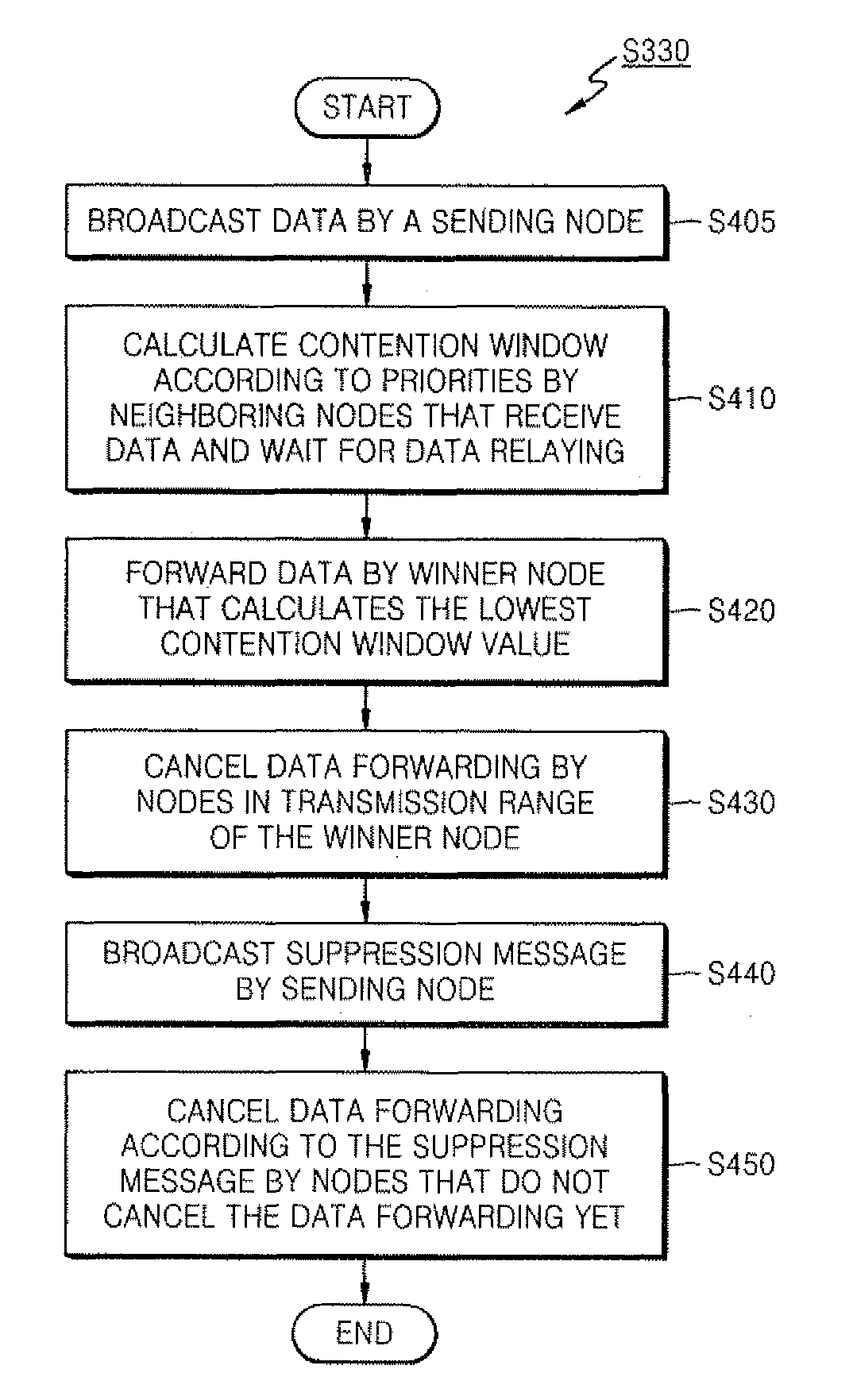
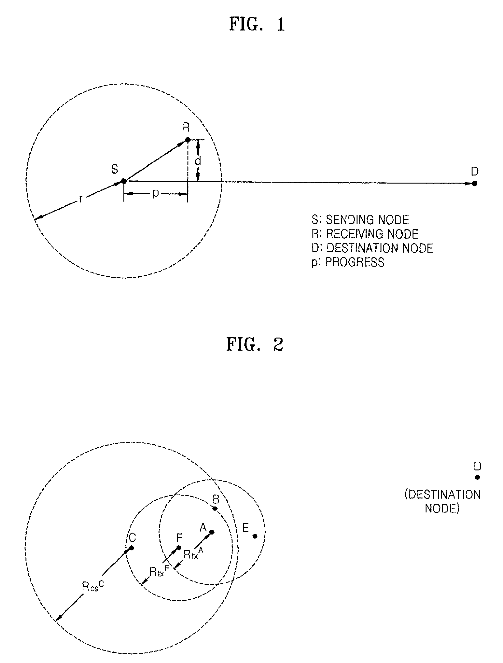
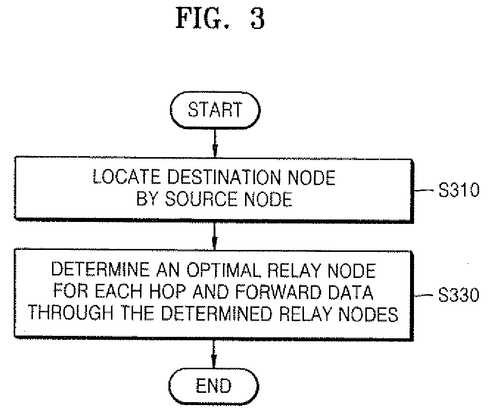
[0016]Hereinafter, exemplary embodiments of the present invention will be described in detail with reference to the attached drawings. A description of technologies that can be easily understood by those of ordinary skill in the art is omitted. FIG. 1 is a view for explaining a definition of a progress used according to the present invention. FIG. 2 is a view illustrating a node configuration for explaining a cross-layer routing method in a wireless sensor network according to the present invention. FIG. 3 is a flowchart of the cross-layer routing method in the wireless sensor network according to the present invention. FIG. 4 is a flowchart illustrating a detailed process of forwarding data (step S330) illustrated in FIG. 3. FIG. 5 is a timing diagram for explaining the cross-layer routing method in the wireless sensor network according to the present invention.

[0017]First, terms used in the present invention are defined. A source node is a node which generates data and transmits t...


PUM


Abstract

Provided is a cross-layer routing method in a wireless sensor network including: locating a destination node which is a final destination of data by a source node which generates the data; and determining an optimal relay node among one or more neighboring nodes using their position information for each hop and forwarding the data from the source node to the destination node through the determined relay nodes. Therefore, an effective and stable routing which reduces overheads of additional control messages used for stable data forwarding and reduces collisions in a shared channel by using wireless link layer characteristics can be implemented.

Description

CROSS-REFERENCE TO RELATED PATENT APPLICATION[0001]This application claims the benefits of Korean Patent Application Nos. 10-2007-0127578 and 10-2008-0066726, respectively filed on Dec. 10, 2007 and Jul. 9, 2008, in the Korean Intellectual Property Office, the disclosures of which are incorporated herein by reference.BACKGROUND OF THE INVENTION[0002]1. Field of the Invention[0003]The present invention relates to an effective and stable routing method significantly reducing overheads of advance information exchange messages which causes degradation in performance of a wireless sensor network in consideration of wireless link characteristics in a wireless sensor network environment.[0004]The present invention is derived from a research project supported by the Information Technology (IT) Research & Development (R&D) program of the Ministry of Information and Communication (MIC) and the Institute for Information Technology Advancement (IITA) [2005-S-038-03, Development of UHF RF-ID and...

Claims


Application Information

Patent Timeline
Patent Type & Authority Patents(United States)
IPC IPC(8): H04J1/10
CPCH04B7/155H04W40/12H04W40/22
Inventor SHIN, CHANG SUBKIM, BONG SOOPYO, CHEOL SIGCHAE, JONG SUKLIM, HYUKJANG, IN HYEOKKIM, HYO JOO
Owner ELECTRONICS & TELECOMM RES INST
Why Eureka
Try Eureka