System and method for detecting flaws in objects using machine vision

a machine vision and object technology, applied in the field of machine vision systems and methods, can solve the problems of mouse bites, defects or otherwise unacceptable, difficult differentiation of such tools, and non-critical surfaces that may contain molding defects, etc., and achieve the effect of greater flexibility in inspection

Active Publication Date: 2012-01-24
COGNEX CORP
View PDF240 Cites 52 Cited by
  • Summary
  • Abstract
  • Description
  • Claims
  • Application Information

AI Technical Summary

Benefits of technology

[0007]This invention overcomes the disadvantages of the prior art by providing a system and method for flexibly detecting flaws in the acquired runtime / live images of objects based upon an inspection process that employs a training or model image of the object. This system and method enables predetermined flaws, and other predetermined features, within predetermined tolerances, to be disregarded as a flaw at inspection time, which affords greater flexibility in the inspection of objects that may have degrees of allowable variability on their surface features.

Problems solved by technology

One drawback with existing inspection tools is that it is often difficult for such tools to differentiate between acceptable process variations between parts and actual flaws in those parts that may render them defective or otherwise unacceptable.
Likewise, certain non-critical surfaces may contain molding defects, or mouse bites.
However, simply detuning the detection criteria (i.e. lowering the system's sensitivity) may cause the system to miss critical flaws or defects, such as cracks in ear teeth, etc.
In addition, there are other reasons that a runtime image of an object may not match that of the trained images, these can include differences in scale, angle of view and illumination between the trained and runtime image.
Some of these translate into perspective distortion, registration errors and non-rigid transformation of object features.
While current machine vision tools can accommodate some of these differences, others may lead to false detection of flaws.

Method used


Image

  • System and method for detecting flaws in objects using machine vision
  • System and method for detecting flaws in objects using machine vision
  • System and method for detecting flaws in objects using machine vision

Examples


Embodiment Construction

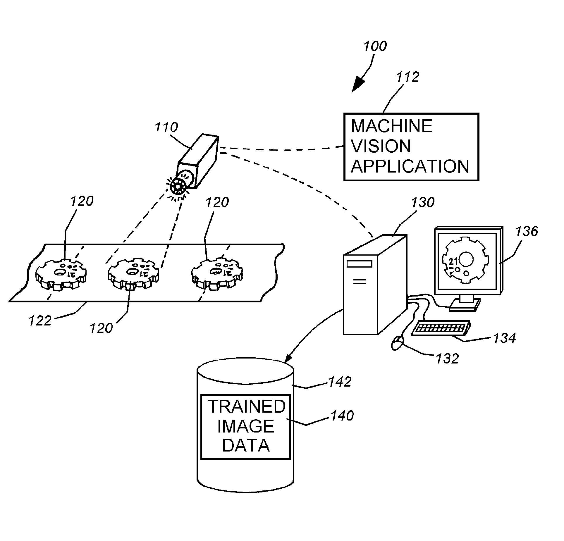
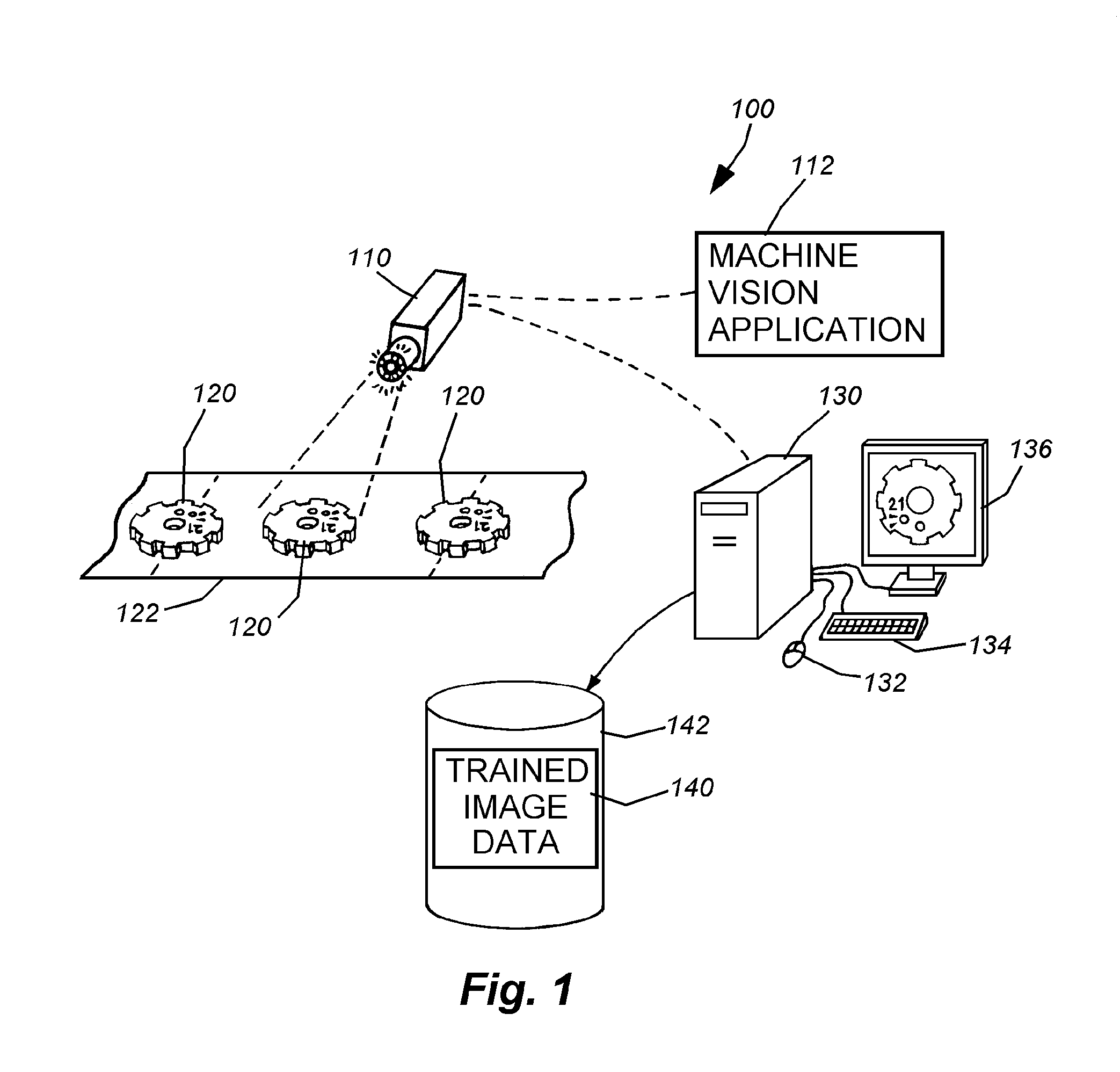
[0024]FIG. 1 details an exemplary machine vision system arrangement 100, which be employed in connection with the principles of this invention. It should be noted that a variety of system implementations can be employed in alternate embodiments. For example, a machine vision detector system in accordance with commonly assigned, copending U.S. Published Patent Application No. US200550275831A1, entitled METHOD AND APPARATUS FOR VISUAL DETECTION AND INSPECTION OF OBJECTS, by William M. Silver (the teachings of which are expressly incorporated by reference), can be employed in an alternate embodiment. As will be described in further detail below, the flexible flaw detection principles and procedures described herein are generally employed subsequent to the global positioning / registration of a live or runtime object image relative to a model or training image of the object, and prior to inspection of the runtime object or feature.

[0025]Referring to FIG. 1, the machine vision system 100 c...


PUM


Abstract

This invention overcomes the disadvantages of the prior art by providing a system and method for flexibly detecting flaws in the acquired runtime/live images of objects based upon an inspection process that employs a training or model image of the object. This system and method enables predetermined flaws, and other predetermined features, within predetermined tolerances, to be disregarded as a flaw at inspection time. Typically, flexible flaw detection and repositioning of the model image occurs locally with respect to predetermined flaws and imperfections, and is undertaken after the image is acquired and the model image has undergone a global affine transformation/positioning with respect to the runtime image. Subsequent inspection then occurs with a locally repositioned model image that subsumes any imperfection or variation that is to be disregarded.

Description

FIELD OF THE INVENTION[0001]This invention relates to machine vision systems and methods, and more particularly to systems and methods for detecting flaws on parts and surfaces based upon trained images.BACKGROUND OF THE INVENTION[0002]Machine vision is used commonly to inspect manufactured objects, parts, printing and other physical items for visible flaws and defects. A variety of systems have been developed to perform such inspection, many of which contain a variety of advanced flaw-detection features and tools. One advanced inspection system is available under the Insight® product line from Cognex Corporation of Natick, Mass. Such systems can be trained with a model image of a desired part appearance, and employ advanced pattern recognition tools to compare the stored model image to the runtime image being inspected.[0003]Two advanced software application are sold under the names PatMax® and Intellect®, and are also available from Cognex Corporation. This application uses advanc...

Claims


Application Information

Patent Timeline
Patent Type & Authority Patents(United States)
IPC IPC(8): G06K9/00
CPCG06T7/001G06T7/0028G06T2207/30164G06T7/33
Inventor ZADEH, ALI MOGHADDAM
Owner COGNEX CORP
Why Eureka
Try Eureka