Apparatus and method for frequency offset monitoring used in digital coherent optical receiver

a technology frequency offset detection, which is applied in the field of digital coherent optical receiver, can solve the problems of inability to guarantee the identical frequency of the laser in the transmitter and the frequency of the laser in the receiver, the method is problematic, and the computational complexity is far higher than the average, so as to reduce computational complexity, stable and precise frequency offset estimation, the effect of reducing the computational complexity

Active Publication Date: 2012-01-24
FUJITSU LTD
View PDF2 Cites 8 Cited by
  • Summary
  • Abstract
  • Description
  • Claims
  • Application Information

AI Technical Summary

Benefits of technology

[0008]The present invention is proposed in view of the aforementioned problems. According to one aspect of the present invention, there is provided a frequency offset estimating method and a frequency offset estimating apparatus used in an optical coherent receiver. The method and apparatus are capable of achieving stable and precise estimation of frequency offsets possibly occurring in a practical system, while the method and apparatus do not include any multiplication operation of complex numbers, thus greatly reducing computational complexity. It is possible in theory for the method to achieve stable and precise detection of frequency offset of any magnitude. Moreover, it is also possible during system design to simplify the frequency offset detecting apparatus in accordance with the symbol rate and the frequency offset detection range as needed, thus further reducing processing complexity.

Problems solved by technology

In practical application, however, it is impossible to guarantee that the frequency of the laser in the transmitter and the frequency of the laser in the receiver are identical, so that there is nonzero intermediate frequency, namely frequency offset, in the baseband electric signal.
This method is problematic in two aspects.
Secondly, the method includes not only multiplication operation of complex numbers but also quartic operation of complex numbers, and such computational complexity is by far higher than that of addition, subtraction and logic operations of real numbers.
Insofar as the current digital signal processing technology is concerned, it is almost impractical to process symbols having rates of up to 10 G symbol / second or 20 G symbol / second in the optical transmission system with such high computational complexity.

Method used


Image

  • Apparatus and method for frequency offset monitoring used in digital coherent optical receiver
  • Apparatus and method for frequency offset monitoring used in digital coherent optical receiver
  • Apparatus and method for frequency offset monitoring used in digital coherent optical receiver

Examples


Embodiment Construction

[0035]Specific embodiments of the present invention are described in greater details below with reference to the accompanying drawings.

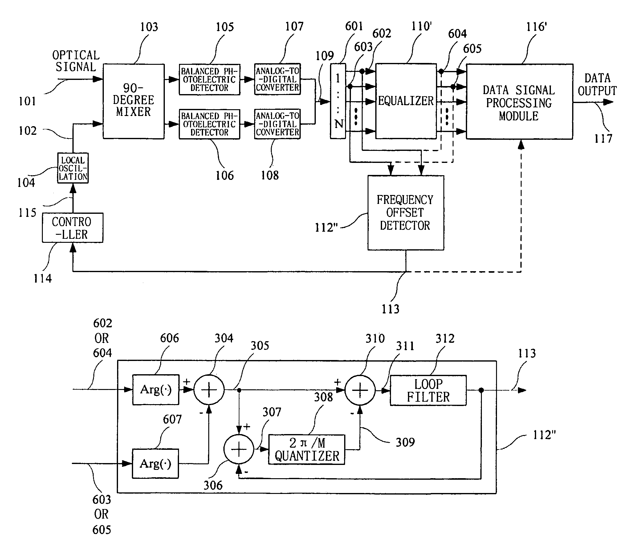
[0036]Signals in a digital coherent optical receiver can be modulated by various modulation modes such as BPSK modulation, QPSK modulation and 8-PSK modulation. The present invention is suitable for application in all these modulation modes. For the sake of brevity, detailed explanation is made below in the case of QPSK modulation.

[0037]FIG. 3 illustrates a frequency offset detecting apparatus 112′ according to one embodiment of the present invention. In the case of QPSK modulation, the kth sampling value of the complex signal 109 (or 111) can be expressed as:

I+jQ=A(k)exp{j[φMOD(k)+φPN(k)+kΔωT]}+nASE(k)

[0038]where A(k) is signal amplitude, ΦMOD(k) is modulation information whose values are ±π / 4, ±3π / 4, ΦPN(k) is phase noise, Δω is frequency offset, T is symbol period, kΔωT is phase gain amount introduced by frequency offset, and nASE(k) is complex Ga...


PUM


Abstract

The present invention discloses a frequency offset detecting apparatus and method for use in a digital coherent optical receiver. The digital coherent optical receiver comprises: a front-end processing section for generating a digital baseband electric signal; an equalizer for performing equalized filtering on the digital baseband electric signal; and the frequency offset detecting apparatus for detecting frequency offset contained in the digital baseband electric signal or frequency offset contained in a signal outputted by the equalizer; wherein the frequency offset detecting apparatus comprises an argument difference obtaining unit, a first subtracter, a second subtracter, a quantizer and an averager, of which the argument difference obtaining unit obtains an argument difference of adjacent symbols in a signal inputted therein; the first subtracter subtracts an output of the averager from the argument difference obtained by the argument difference obtaining unit; the quantizer performs uniform quantization with predetermined intervals on an output of the first subtracter; the second subtracter subtracts an output of the quantizer from the argument difference obtained by the argument difference obtaining unit; and the averager averages an output of the second subtracter.

Description

CROSS REFERENCE TO RELATED APPLICATIONS[0001]This application claims the benefit of Chinese Application No. 200810090227.4, filed Apr. 1, 2008 in the State Intellectual Property Office of the P.R. China, the disclosure of which is incorporated herein by reference.FIELD OF THE INVENTION[0002]The present invention relates to a digital coherent optical receiver, and more particularly, to a frequency offset detecting apparatus and method used in a digital coherent optical receiver.BACKGROUND OF THE RELATED ART[0003]In comparison with conventional intensity modulation-direct detection or phase modulation-delayed interference detection technologies, coherent optical communication technology can tolerate lower optical signal-to-noise ratio,. compensate linear damage by using digital signal processing technology, and achieve higher spectral usability. These advantages of the coherent optical communication technology satisfy the demand on higher single wavelength rate and higher spectral eff...

Claims


Application Information

Patent Timeline
Patent Type & Authority Patents(United States)
IPC IPC(8): H04B10/06H04B10/07H04B10/293H04B10/079H04B10/2507H04B10/516H04B10/548H04B10/564H04B10/572H04B10/61
CPCH04B10/61H04B10/6161H04B10/6164H04B10/63
Inventor ZHANG, HUIJIANLI, LEITAO, ZHENNINGNAKASHIMA, HISAO
Owner FUJITSU LTD
Why Eureka
Try Eureka