Firearm accessory rail with integral sight elements

a technology of sight elements and accessory rails, applied in the field of rails, can solve the problems of too large consequences of scope or lighted sight system failure, add complexity, cost, weight and bulk to the weapon system,

Inactive Publication Date: 2012-01-31
MCCANN DEBRA D
View PDF35 Cites 25 Cited by
  • Summary
  • Abstract
  • Description
  • Claims
  • Application Information

AI Technical Summary

Problems solved by technology

For some users, the consequences of a scope or lighted sight system failure are too great not to have some kind of pre-aligned back up iron sights (BUIS) in place in addition to whatever optics are mounted on the accessory rail.
These, however, add complexity, cost, weight and bulk to the weapon system.
As another example, a shotgun may be used for hunting with a rail-mounted scope, but may also be used for home defense where a magnifying scope is undesired.

Method used


Image

  • Firearm accessory rail with integral sight elements
  • Firearm accessory rail with integral sight elements
  • Firearm accessory rail with integral sight elements

Examples


Embodiment Construction

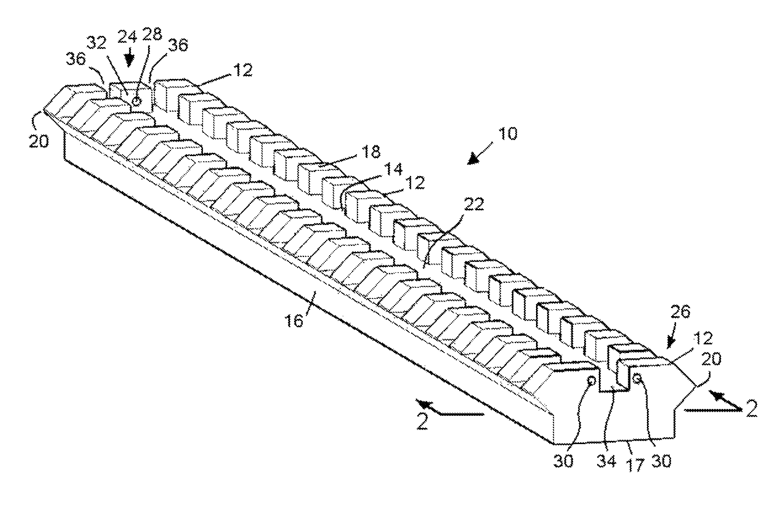
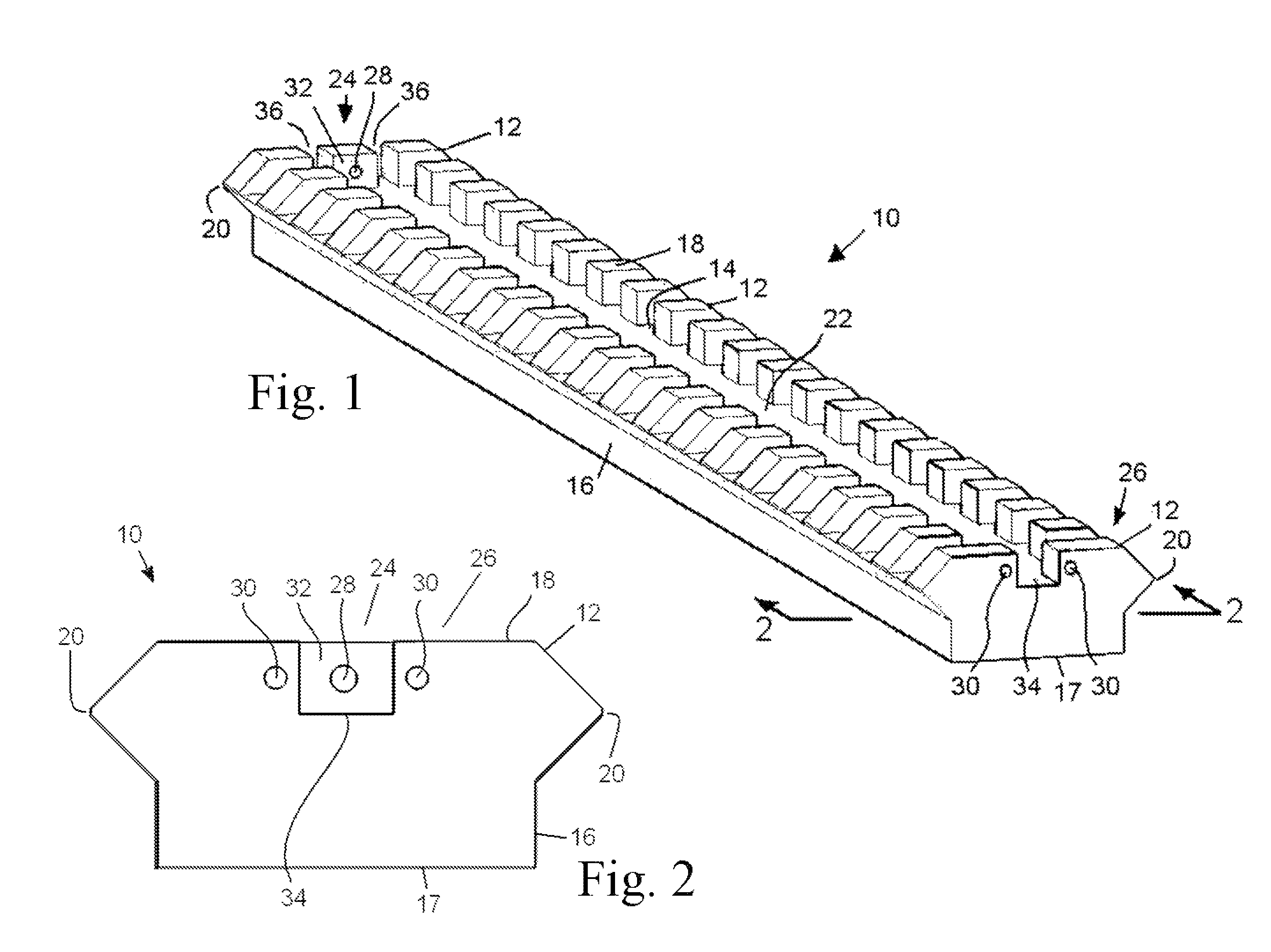
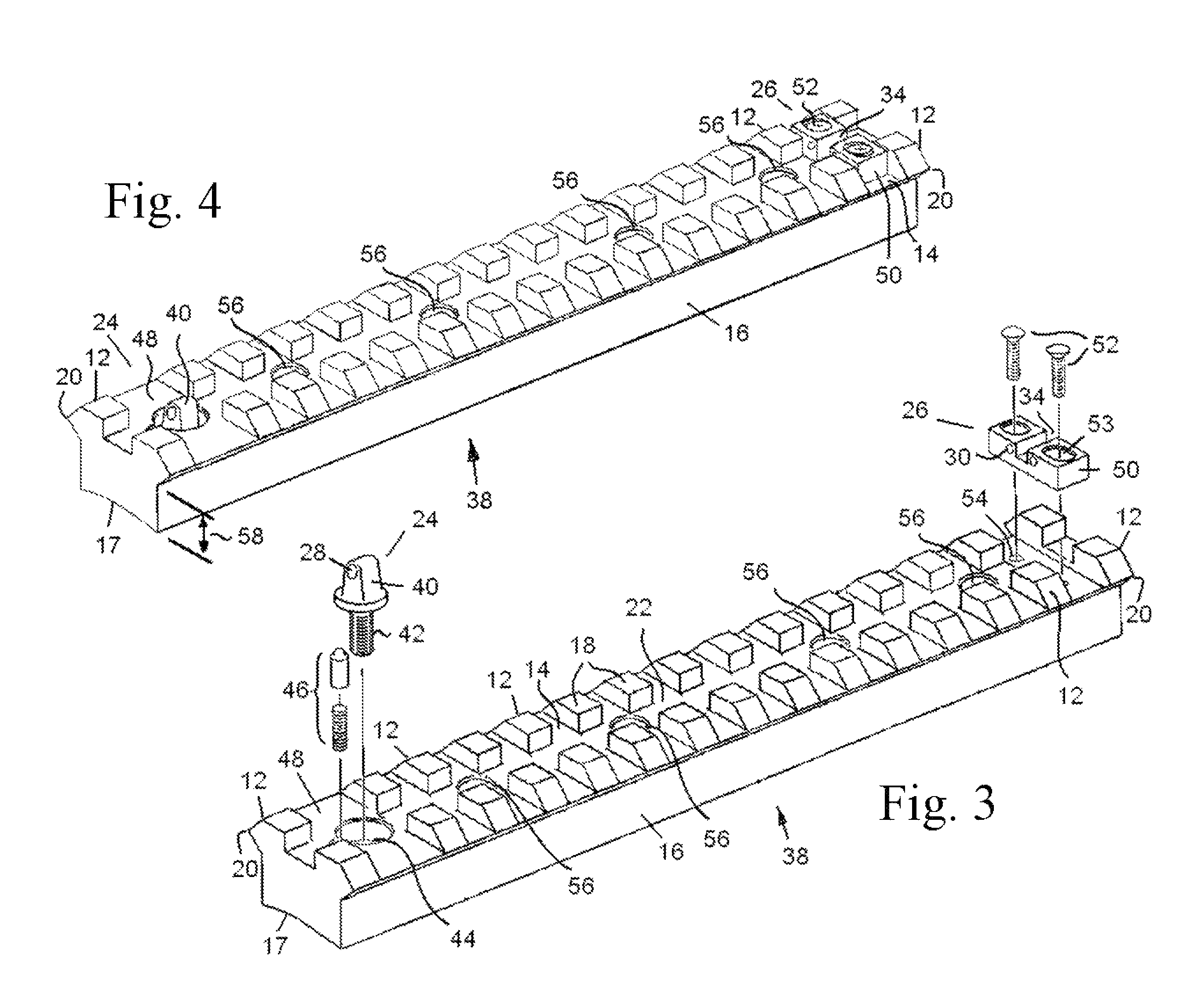
[0027]Referring to the various figures of the drawings and first to FIG. 1, therein is shown at 10 an accessory mounting rail with an integrated back up sight according to a first preferred embodiment of the present invention. The rail 10 is an elongated member having a series of laterally-extended lugs 12 with spacing slots 14 there-between. The lugs 12 are supported by a base portion 16 and present a dovetail or chamfered T-shaped profile in cross section. The base 16 may be independent or integrated into a firearm receiver, barrel shroud, stock or other implement. If the rail 10 is a separate fixture and is to be to be secured in place on a firearm, the base 16 may be shaped to engage any desired surface. For example, the bottom surface 17 may be flat or curved to fit closely and firmly onto a corresponding surface. The lugs 12 provide coplanar top surfaces 18 which present a platform on which accessories (not shown), such as an optic device, scope rings, or illumination device m...


PUM


Abstract

A firearm accessory mounting rail with an integrated back up sight system including an elongated Picatinny rail having longitudinally spaced apart first and second end regions and a transverse profile. A first sight element has a visual marker substantially centrally positioned. A second sight element has laterally spaced apart visual markers. A substantially centered longitudinal channel extends along the upper surface of the rail between the first and second sight elements. The firearm may be sighted by visually aligning the marker of the first sight element between the markers of the second sight element, the visual alignment being at least partially through the longitudinal channel. The sight elements may be defined completely within the transverse profile of the rail so as not to interfere with the normal attachment of any accessories to the rail and may be adjustable for windage and / or elevation. The visual markers may be illuminated by light gathering fiber optic or tritium elements.

Description

TECHNICAL FIELD[0001]The present invention relates to a rail for mounting optics or other accessories to a firearm, the mounting rail having integral sighting elements. More specifically, it relates to the integration of back-up or “iron” sights into a mounting rail in a manner that does not interfere with the mounting of accessories.BACKGROUND[0002]Standardized accessory mounting rails are well known for use with firearms. Most common is the Picatinny, Weaver, or MIL-STD 1913 rail, referred to herein collectively or interchangeably as a “Picatinny” rail or mounting rail. A Picatinny rail can range in length from less than one inch, such as for mounting a light or laser indicator to the underside of a pistol frame or for mounting a single scope ring, to the full length of a rifle. Typically, these standardized accessory attachment rails are formed or secured along the length of the frame, stock, or barrel parallel to the bore of the firearm barrel so that any sighting device, scope,...

Claims


Application Information

Patent Timeline
Patent Type & Authority Patents(United States)
IPC IPC(8): F41G1/00
CPCF41G1/033F41G1/10F41G1/16F41G11/003
Inventor MCCANN, RICHARD J.
Owner MCCANN DEBRA D
Why Eureka
Try Eureka