Centrifugal chopper pump with impeller assembly

a centrifugal pump and impeller technology, applied in the direction of positive displacement liquid engine, vessel construction, marine propulsion, etc., can solve the problems of motor protection control trip, motor overload, chopping down time, etc., and achieve the effect of improving solid waste pump, additional structural and operating advantages

Active Publication Date: 2012-01-31
VAUGHAN
View PDF21 Cites 23 Cited by
  • Summary
  • Abstract
  • Description
  • Claims
  • Application Information

AI Technical Summary

Benefits of technology

[0009]There is disclosed herein an improved solid waste pump design which avoids the disadvantages of prior devices while affording additional structural and operating advantages.
[0011]In another embodiment, the impeller includes a back shroud and cutting blades sharpened on a first edge extending opposite the back shroud and fixed on a first surface of the back shroud. The at least one pump-out vane is preferably fixed to a second surface of the back shroud opposite the first surface, while the end plate includes a surface adjacent to and facing the first edge of the cutting blades. The end plate may include one or more stationary shear fingers at the pump intake opening and may also include one or more internal cutting grooves cut into the end plate surface for a shearing operation in combination with the sharpened edge of the cutting blades of the impeller. The two shearing operations are capable of working together to efficiently reduce solid material within the pump.

Problems solved by technology

One of the problems with each of these devices is the occurrence of motor overloading during heavy chopping.
Where the chopping is not efficient, the motor power increases causing the motor protection controls to trip the motor offline.
The chopping down-time, of course, detracts from the cost effectiveness of the process.
Another problem relates to excessive wear on the cutting parts over time.
Fibrous material, such as hair and the like, tend to accumulate in the cutting area, particularly at the cutting parts.
The fibrous material collects grit and sand causing the cutting parts to grind down prematurely.

Method used


Image

  • Centrifugal chopper pump with impeller assembly
  • Centrifugal chopper pump with impeller assembly
  • Centrifugal chopper pump with impeller assembly

Examples


Embodiment Construction

[0029]While this invention is susceptible of embodiments in many different forms, there is shown in the drawings and will herein be described in detail a preferred embodiment of the invention with the understanding that the present disclosure is to be considered as an exemplification of the principles of the invention and is not intended to limit the broad aspect of the invention to embodiments illustrated.

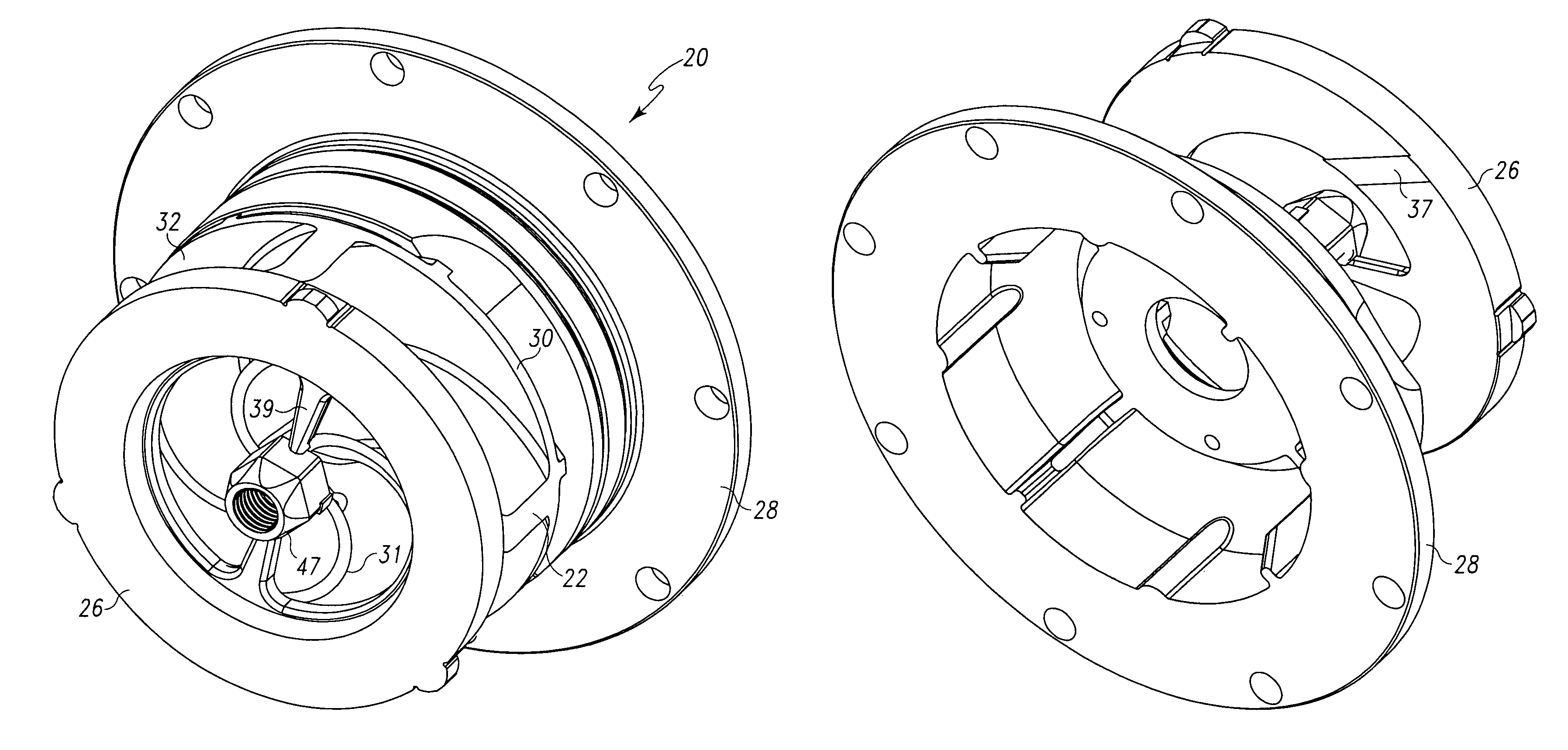
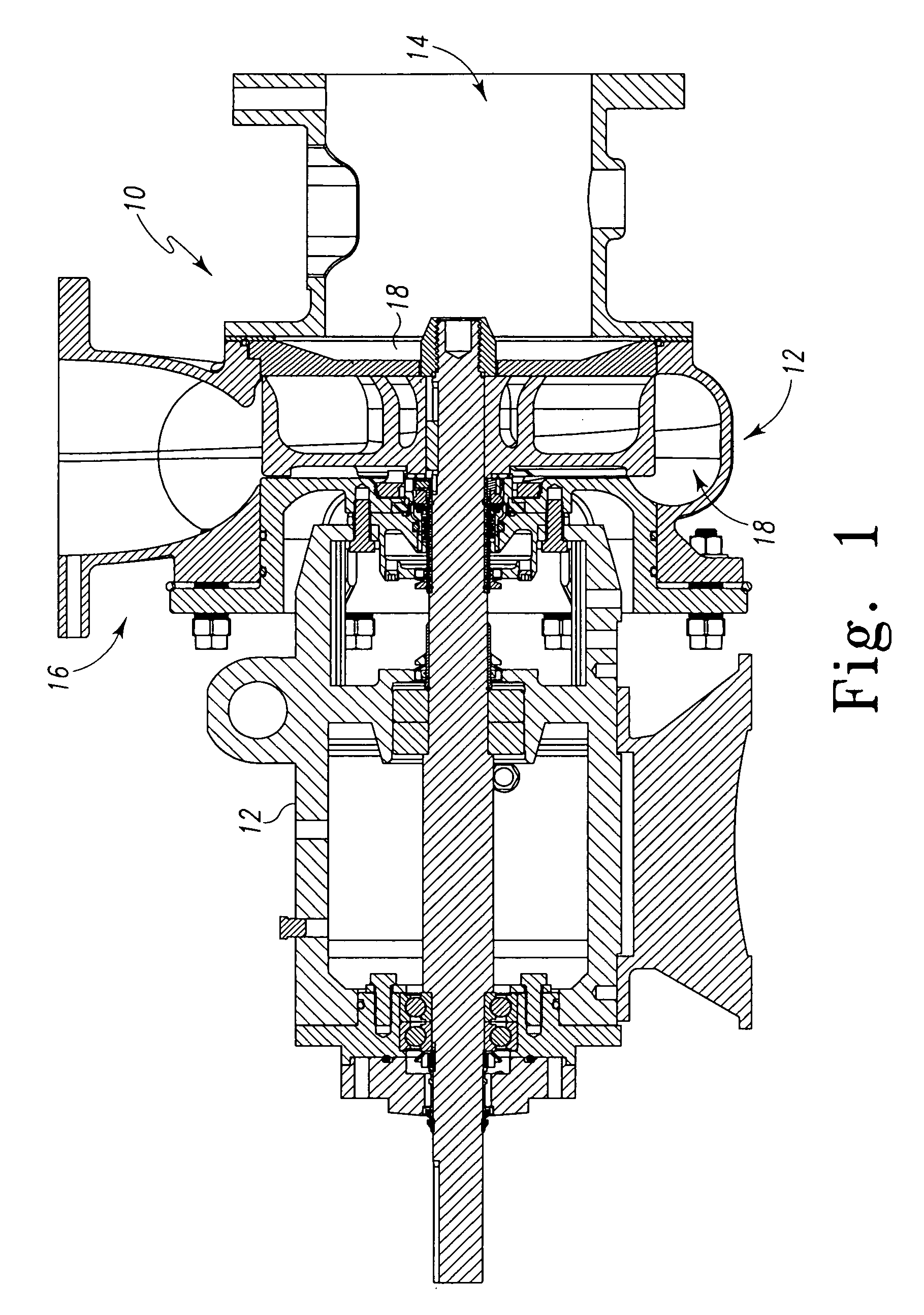
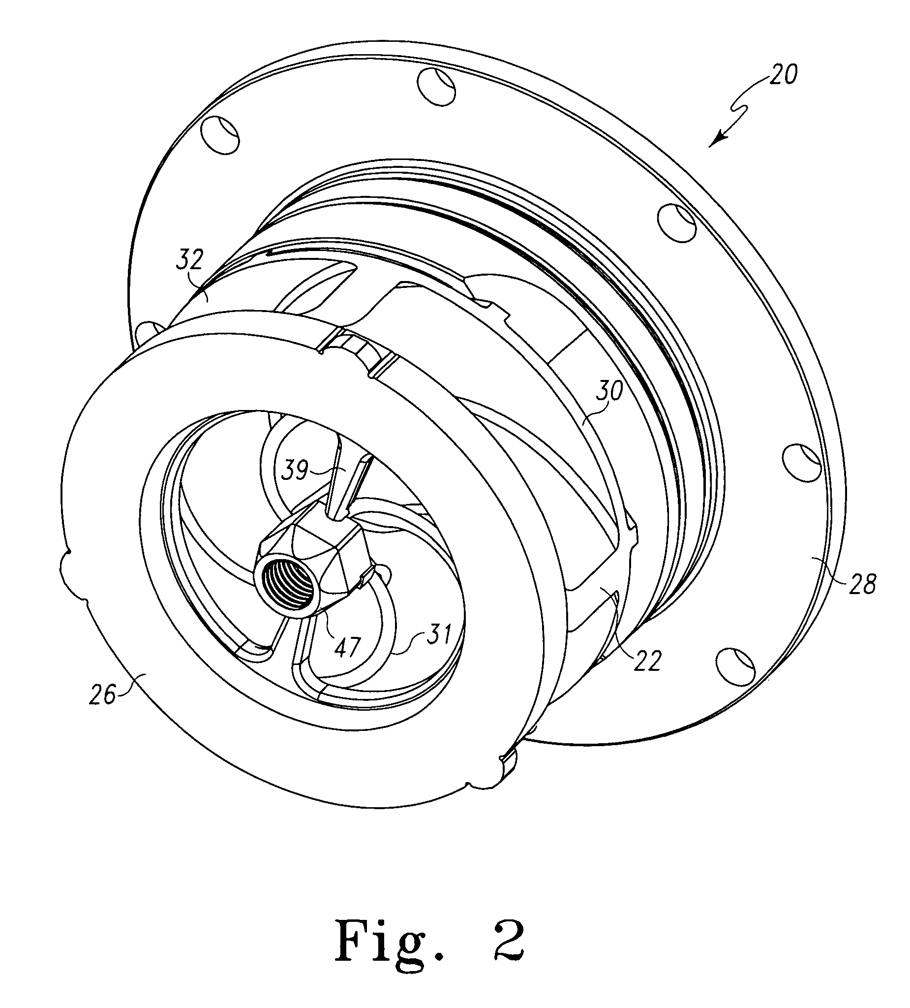
[0030]Referring to FIGS. 1-15, there is illustrated a chopper pump, generally designated by the numeral 10. The chopper pump 10 has a housing 12 having an intake opening 14 and an outlet opening 16, both in fluid communication with an internal chamber 18. A similar chopper pump is illustrated and disclosed in U.S. Pat. No. 5,460,482 to Dorsch, the patent being assigned to the Assignee of the present invention. To the extent an understanding of the construction and operation of the present invention is aided by the '482 patent, the same is hereby incorporated by reference.

[0031]As ...


PUM


Abstract

The disclosed solid waste pump is a chopper pump, and preferably a chopper pump having a small rated motor and a semi-open impeller design. Particularly, a chopper pump having an impeller, at least one pump-out vane, an end plate, and a back plate including at least one cutting rib is disclosed. The impeller includes a back shroud and cutting vanes sharpened on a first edge extending opposite the back shroud and fixed on a first surface of the back shroud. The at least one pump-out vane is preferably fixed to a second surface of the back shroud opposite the first surface, while the end plate includes a surface adjacent to and facing the first edge of the cutting vanes and at least one internal cutting rib fixed to the end plate surface for shearing operation in combination with the sharpened edge of the cutting vanes of the impeller. Finally, the back plate has a surface adjacent to and facing the at least one pump-out vane and at least one cutting rib attached to the back plate surface for shearing operation in combination with the at least one pump-out vane.

Description

TECHNICAL FIELD OF THE INVENTION[0001]The present device relates to a centrifugal pump effective for pumping liquids and slurries containing solid matter, including various types of refuse, and for chopping the solid matter which may thereafter be processed for disposal. Particularly, the device relates to a chopper pump which both effectively allows the pump to continue working during heavy chopping and efficiently reduces wear on components due to the presence of grit-like material in the liquid.BACKGROUND OF THE INVENTION[0002]Generally speaking, U.S. Pat. No. 3,155,046 to Vaughan, issued Nov. 3, 1964, discloses a centrifugal pump having an open impeller with radial vanes. The vane edges adjacent to the pump inlet cooperate with sharpened edges of inlet apertures to cut stringy material or chunks entering the pump. Similarly, U.S. Pat. No. 3,973,866 to Vaughan, issued Aug. 10, 1976, and U.S. Pat. No. 4,842,479 to Dorsch, issued Jun. 27, 1989, disclose centrifugal pumps having imp...

Claims


Application Information

Patent Timeline
Patent Type & Authority Patents(United States)
IPC IPC(8): F01D25/00F03D11/00F03D11/02F04B23/14F04D29/38
CPCF04D7/045F04D29/2288
Inventor DORSCH, GLENN ROBERTKEERAN, KENT HARRISON
Owner VAUGHAN
Why Eureka
Try Eureka